
 English
 中文简体
中文简体What Does a Transformer Do?
2026-03-13
Content
- 1 The Core Answer
- 2 Types of Transformers and Their Applications
- 3 Current Transformer Connection: How It Works and Why It Matters
- 4 Pad Mount Transformer: Installation and Key Considerations
- 5 Transformer and Substation: How They Work Together
- 6 How to Check a Transformer: Testing Methods and What to Look For
- 7 Choosing the Right Transformer for Your Application
The Core Answer
A transformer transfers electrical energy between two or more circuits through electromagnetic induction, changing voltage levels without altering the frequency. In practical terms, it steps voltage up for long-distance transmission (e.g., from 11 kV to 400 kV) or steps it down for safe end-use (e.g., from 240 V to 12 V for electronics). Beyond voltage conversion, transformers also provide electrical isolation, regulate current, and protect equipment from surges.
Modern transformers achieve efficiencies of 95% to 99%, making them among the most efficient electrical devices in use. Whether in a utility substation handling hundreds of megavatts or a compact unit inside a phone charger, the underlying principle—Faraday's law of electromagnetic induction—remains the same.
Types of Transformers and Their Applications
Transformers are broadly categorized by operating frequency, construction, and application. Understanding the distinctions helps in selecting the right unit for any given system.
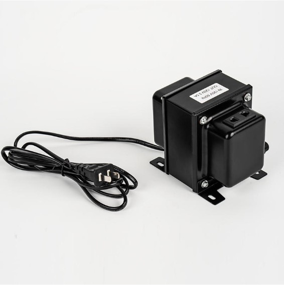
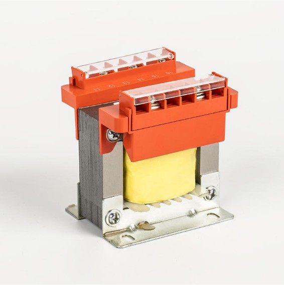
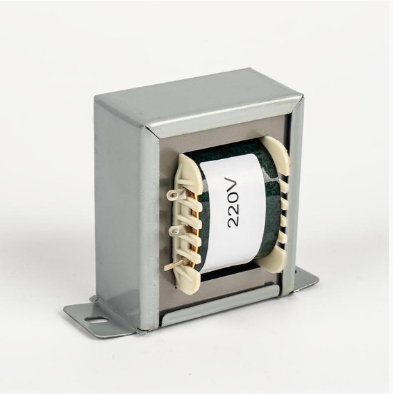
Low Frequency Transformers
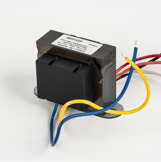
Low frequency transformers operate at the standard power grid frequency of 50 Hz or 60 Hz. They use laminated silicon steel cores to minimize eddy current losses. Their key advantages include robustness, high power handling capacity, and long service life—often exceeding 25 years with proper maintenance.
Applications of low frequency transformers span a wide range of industries:
- Power distribution: Grid substations stepping down from transmission voltage to consumer voltage
- Industrial control: Voltage regulators, stabilizers, and electric welders requiring stable, high-current output
- Lighting and home appliances: Dimming systems, HVAC compressor drives, and refrigeration units
- New energy: Photovoltaic (PV) inverters converting DC from solar panels into grid-compatible AC, and energy storage systems managing charge/discharge cycles
Ningbo Chuangbiao Electronic Technology Co., Ltd. specializes in low frequency transformers engineered for these demanding environments, offering products that ensure efficient power conversion and reliable protection across power, industrial, lighting, home appliance, and new energy sectors.
High Frequency Transformers
High frequency transformers operate from 20 kHz up to several MHz. Because core losses increase with frequency for iron cores, they use ferrite or powdered iron cores instead. The major benefit is size: a high-frequency transformer handling the same power as a 50 Hz unit can be 10 to 100 times smaller and lighter.
Typical applications include switched-mode power supplies (SMPS), telecommunications equipment, medical devices, and electric vehicle (EV) onboard chargers.
| Feature | Low Frequency (50/60 Hz) | High Frequency (20 kHz+) |
|---|---|---|
| Core Material | Laminated silicon steel | Ferrite / Powdered iron |
| Size & Weight | Larger and heavier | Compact and lightweight |
| Efficiency | 95–99% | 85–95% |
| Typical Use | Grid, industrial, renewables | SMPS, telecom, EV chargers |
| Surge Tolerance | Excellent | Moderate |
| Lifespan | 20–30+ years | 5–15 years |
Current Transformer Connection: How It Works and Why It Matters
A current transformer (CT) is a measurement device that produces a reduced, proportional current in its secondary winding, allowing safe measurement of high-current circuits. Correct connection is critical for both accuracy and safety.
Standard CT Connection Procedure
- Pass the primary conductor (the line being measured) through the CT window or connect to the primary terminals (P1, P2).
- Connect the secondary terminals (S1, S2) to the measuring instrument—typically a 5 A or 1 A rated ammeter or energy meter.
- Never leave the secondary of an energized CT open-circuited. An open secondary can generate dangerously high voltages (potentially thousands of volts) due to the unimpeded magnetomotive force.
- Observe polarity markings (dot convention or P1/S1 markings) to ensure correct phase relationships for protective relay applications.
- Ground one secondary terminal per standard practice (typically S2 or S1 grounded to chassis) to prevent floating voltage hazards.
Common CT ratios are 100:5, 200:5, 400:5, and 1000:5 A. Selecting an undersized CT ratio causes saturation and measurement errors; oversizing reduces accuracy at normal load. Always specify CT accuracy class (e.g., Class 0.5 for metering, Class 5P for protection) when ordering.
Pad Mount Transformer: Installation and Key Considerations
A pad mount transformer is a ground-level, tamper-resistant unit housed in a locked steel cabinet, connected to an underground distribution network. It is the standard solution for suburban and commercial areas where aerial lines are impractical or undesirable.
Typical ratings range from 25 kVA to 2,500 kVA, with primary voltages of 4 kV to 35 kV and secondary voltages of 120/240 V (single-phase) or 208Y/120 V to 480Y/277 V (three-phase).
Key Installation Requirements
- Concrete pad: Must be level, structurally rated, and sized per manufacturer specs (typically extending 3–6 inches beyond the cabinet footprint).
- Clearance: Minimum 3 feet of clear working space on the high-voltage side; 10 feet clearance from buildings per NEC guidelines.
- Cable routing: Underground cables enter through conduit sleeves sealed against moisture and rodents.
- Grounding: The cabinet and neutral must be bonded to a ground rod driven to local soil resistance requirements (typically <25 Ω).
- Oil containment: Many jurisdictions require a secondary containment berm or absorbent pad beneath oil-filled units to prevent soil contamination.
Transformer and Substation: How They Work Together
A substation is a facility that switches, transforms, and regulates electrical power. Transformers are its central components, performing the actual voltage conversion between transmission and distribution levels.
A typical utility substation workflow looks like this:
- Transmission line input: Power arrives at 115 kV, 230 kV, or 500 kV from the generating plant.
- Step-down transformer: A large power transformer reduces voltage to 12.47 kV, 13.8 kV, or 34.5 kV for primary distribution.
- Switchgear and protection: Circuit breakers, disconnect switches, and protective relays isolate faults within milliseconds.
- Distribution transformers: Pole-mounted or pad-mounted units further reduce voltage to 120/240 V or 480 V for residential and commercial use.
A single substation power transformer can handle 10 MVA to 1,000 MVA and weighs up to several hundred tons. Failure of such a unit can black out an entire region for weeks, which is why substation transformer monitoring and maintenance are treated as critical infrastructure tasks.
How to Check a Transformer: Testing Methods and What to Look For
Regular testing prevents unexpected failures and extends transformer service life. The appropriate test depends on the transformer type and available equipment.
Basic Visual and Physical Checks
- Inspect for oil leaks, corrosion, cracked bushings, or damaged cooling fins.
- Check oil level through the sight glass; low oil reduces cooling and dielectric strength.
- Listen for unusual humming, buzzing, or crackling—sounds above the normal 100–120 Hz hum may indicate core looseness or partial discharge.
- Verify that cooling fans or pumps (if present) are operating correctly.
Electrical Tests
- Turns Ratio Test (TTR): Confirms the ratio of primary to secondary voltage matches the nameplate. Acceptable deviation is typically ±0.5% of nameplate ratio.
- Insulation Resistance (IR) Test: Apply 500 V or 1,000 V DC via a megohmmeter between windings and between windings and core. Values above 1,000 MΩ are generally considered healthy for medium-voltage units.
- DC Winding Resistance: Detects shorted turns or loose connections. Compare measured values against factory data; deviations over 2% warrant investigation.
- Dissolved Gas Analysis (DGA): For oil-filled transformers, identifies incipient faults by measuring gases dissolved in the insulating oil (e.g., acetylene indicates arcing, hydrogen indicates partial discharge).
- Power Factor / Tan Delta Test: Measures dielectric losses in insulation. Values exceeding 0.5%–1% for oil-paper insulation systems suggest moisture ingress or aging.
Recommended Maintenance Intervals
| Test / Inspection | Frequency | Primary Goal |
|---|---|---|
| Visual Inspection | Monthly | Detect leaks, damage, overheating |
| Oil Level & Temperature | Monthly | Ensure cooling sufficiency |
| Insulation Resistance | Annually | Assess insulation health |
| Turns Ratio Test | Every 3–5 years | Verify winding integrity |
| Dissolved Gas Analysis | Annually (oil units) | Detect incipient internal faults |
| Full Electrical Testing | Every 5–10 years | Comprehensive condition assessment |
Choosing the Right Transformer for Your Application
Selecting a transformer involves matching several parameters to the load and environment. Undersizing causes overheating and premature failure; oversizing wastes capital and increases no-load losses.
- kVA Rating: Calculate the total connected load (in kW) divided by the power factor, then add a 20–25% safety margin for future expansion.
- Voltage Ratio: Match primary voltage to supply and secondary voltage to the load requirement; confirm tap-changer range if supply voltage varies.
- Insulation Class: Choose dry-type for indoor, fire-sensitive locations (e.g., hospitals, high-rises); oil-immersed for outdoor substations where higher ratings are needed.
- Operating Frequency: Confirm 50 Hz or 60 Hz compatibility—a transformer designed for 60 Hz will overheat and saturate if operated at 50 Hz at the same voltage.
- Environmental Conditions: For humid, corrosive, or high-altitude environments, specify encapsulated windings, tropical coating, or altitude-derated units.
For industrial and new energy applications demanding proven low frequency transformer performance, Ningbo Chuangbiao Electronic Technology Co., Ltd. provides engineered solutions—from welding transformers and voltage regulators to PV inverter transformers and energy storage system units—backed by rigorous quality standards and deep application expertise.


Welcome To CHUANGBIAO
Address : No.420-3, Sanbei East Road, Guanhaiwei Industrial Zone, Cixi City, Ningbo, Zhejiang, China
Contact
- Tel: +86 186 6825 0703
- Email: linjian@nbcbdz.com
About us
Products
Copyright © Ningbo Chuangbiao Electronic Technology Co., Ltd.
All Rights Reserved. EI Transformer Manufacturer


