
 English
 中文简体
中文简体How Transformers Work: Types, Structure, Applications & Limitations
2026-03-20
Content
- 1 What Are Transformers?
- 2 Historical Context: How Transformers Came to Power the World
- 3 Transformer Basics: Voltage, Turns Ratio, and Efficiency
- 4 Transformer Structure: Core Components Explained
- 5 How Transformers Work: Step-by-Step Electromagnetic Process
- 6 Low Frequency Transformer vs. High Frequency Transformer
- 7 Key Applications of Transformers Across Industries
- 8 Transformer Drawbacks and Limitations
- 9 Conclusion: Choosing the Right Transformer for Your Application
What Are Transformers?
A transformer is an electrical device that transfers energy between two or more circuits through electromagnetic induction, enabling voltage conversion, current regulation, and electrical isolation without any direct electrical connection. At its core, a transformer consists of two or more coils of wire (windings) wrapped around a shared magnetic core. When alternating current flows through the primary winding, it generates a changing magnetic field that induces a voltage in the secondary winding — this is Faraday's Law of Electromagnetic Induction in action.
Transformers are broadly categorized by their operating frequency into two major types: low frequency transformers (typically operating at 50–60 Hz) and high frequency transformers (operating from a few kHz up to several MHz). Both types are indispensable across power systems, industrial equipment, consumer electronics, and renewable energy infrastructure.
Historical Context: How Transformers Came to Power the World
The transformer was first demonstrated in 1831 by Michael Faraday, who discovered electromagnetic induction. The practical transformer as we know it today was developed in the 1880s by engineers including Lucien Gaulard, John Dixon Gibbs, William Stanley Jr., and the team at Westinghouse. The "War of Currents" between Edison's DC system and Tesla/Westinghouse's AC system was decisively won by AC — largely because transformers could step voltage up for long-distance transmission and then step it back down for safe household use, something DC technology at the time could not achieve efficiently.
By the early 20th century, transformers formed the backbone of electrical grids worldwide. Today, from tiny ferrite-core transformers inside a smartphone charger to massive 1,000 MVA units in national grid substations, transformer technology underpins virtually all modern electrical infrastructure.
Transformer Basics: Voltage, Turns Ratio, and Efficiency
The fundamental operation of a transformer is governed by the turns ratio — the ratio of the number of turns in the primary winding (N₁) to the secondary winding (N₂):
- Step-up transformer: N₂ > N₁ → Secondary voltage is higher than primary voltage (e.g., power plant output stepped up to 400 kV for long-distance transmission)
- Step-down transformer: N₂ < N₁ → Secondary voltage is lower than primary voltage (e.g., 11 kV distribution stepped down to 230 V for homes)
- Isolation transformer: N₁ = N₂ → Same voltage on both sides, used for electrical safety and noise isolation
The voltage relationship is: V₁/V₂ = N₁/N₂. Consequently, current transforms inversely: I₁/I₂ = N₂/N₁. Modern power transformers achieve efficiencies of 95%–99.5%, making them among the most efficient electrical machines ever built. Losses arise from two sources: copper losses (I²R heating in windings) and core losses (hysteresis and eddy current losses in the magnetic core).
Transformer Structure: Core Components Explained
Understanding how a transformer works requires knowing its key structural components:
Magnetic Core
The core channels the magnetic flux between windings. Low frequency transformers use laminated silicon steel cores (0.25–0.5 mm thick sheets) to minimize eddy current losses at 50/60 Hz. High frequency transformers use ferrite cores or powdered iron cores, which have lower core losses at kHz–MHz frequencies. Core geometry varies — common shapes include E-I cores, toroidal cores, and U-I cores, each with specific advantages in flux efficiency, winding ease, and EMI shielding.
Primary and Secondary Windings
Windings are coils of insulated copper (or sometimes aluminum) wire wound around the core. The primary winding receives input AC power; the secondary delivers output power. Multi-winding designs can provide multiple output voltages simultaneously. Insulation class (A, B, F, H) determines the maximum permissible temperature — Class H insulation tolerates up to 180°C, suited for high-load industrial transformers.
Insulation and Cooling Systems
Large power transformers are immersed in mineral oil or synthetic ester fluid for both insulation and heat dissipation. Smaller dry-type transformers use air cooling or resin encapsulation (cast resin transformers). Oil-cooled units can deploy forced oil and air cooling (OFAF) systems to handle ratings up to 1,000 MVA and beyond.
How Transformers Work: Step-by-Step Electromagnetic Process
- AC voltage is applied to the primary winding, driving alternating current through it.
- This alternating current creates a time-varying magnetic flux in the core, proportional to the applied voltage and inversely proportional to frequency and number of turns (Faraday's Law: V = N × dΦ/dt).
- The magnetic flux is efficiently channeled through the core to the secondary winding.
- The changing flux induces an EMF (electromotive force) in the secondary winding — the output voltage — determined by the turns ratio.
- When a load is connected to the secondary, current flows, and the transformer automatically adjusts its primary current to maintain energy balance (minus losses).
This process is entirely passive — no moving parts, no active switching in a conventional transformer — which is why transformers deliver exceptional reliability and long operational lifespans, often 25–40 years for well-maintained power transformers.
Low Frequency Transformer vs. High Frequency Transformer
The distinction between low and high frequency transformers goes beyond just operating frequency — it affects core material, physical size, efficiency profile, and application suitability.
| Feature | Low Frequency Transformer | High Frequency Transformer |
|---|---|---|
| Operating Frequency | 50–60 Hz (mains frequency) | 1 kHz – several MHz |
| Core Material | Laminated silicon steel | Ferrite, powdered iron, amorphous alloy |
| Physical Size | Larger and heavier | Compact and lightweight |
| Typical Efficiency | 95%–99.5% at rated load | 85%–98% (varies by design) |
| Surge Tolerance | Very high; handles surges well | Moderate; requires protection circuits |
| Typical Applications | Power grids, welders, industrial drives, UPS, PV inverters | SMPS, telecom, medical devices, EV chargers |
| Relative Cost Structure | Higher material cost, simpler electronics | Lower material cost, complex control electronics |
Low Frequency Transformer: Strengths and Use Cases
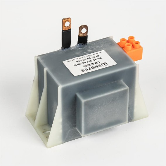
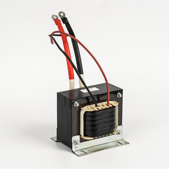
Low frequency transformers operate directly on utility AC power (50 or 60 Hz) and are renowned for their reliability, electrical isolation quality, and ability to handle high surge currents. They are the workhorses of power distribution, industrial automation, electric welding, and renewable energy systems. A 100 kVA low frequency isolation transformer in a solar inverter system, for example, not only converts DC-derived AC to grid voltage but also provides galvanic isolation that protects both the inverter and the grid from fault currents.
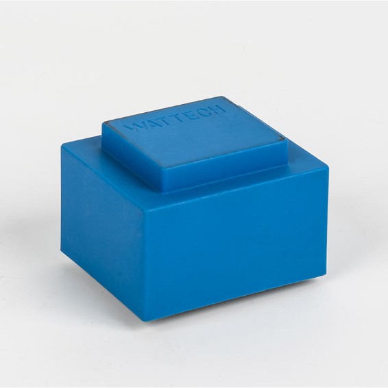
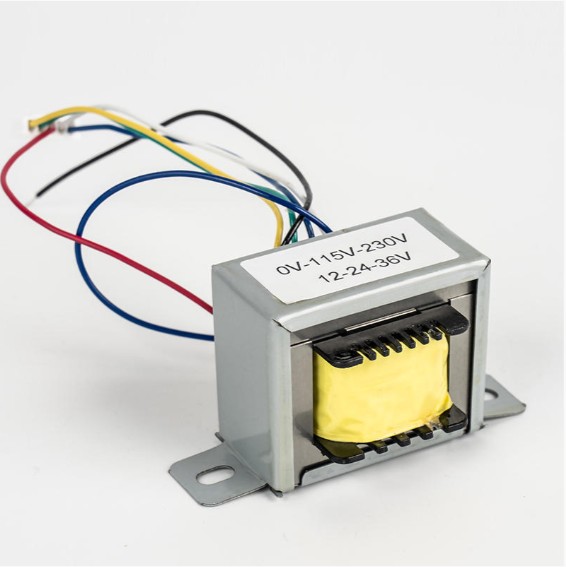
Ningbo Chuangbiao Electronic Technology Co., Ltd. has built its reputation in this domain. As a leader in low frequency transformer manufacturing, the company engineers products for applications spanning voltage regulators, electric welders, photovoltaic inverters, energy storage systems, HVAC, and home appliances. In welding equipment, their transformers deliver stable welding voltage and current critical for consistent weld quality. In photovoltaic inverters, their units convert DC power from solar panels into grid-compatible AC, while providing the galvanic isolation required by most national grid codes. In battery energy storage systems, bidirectional low frequency transformers handle both charging and discharging cycles, enhancing the overall efficiency of renewable energy integration.
High Frequency Transformer: Strengths and Use Cases
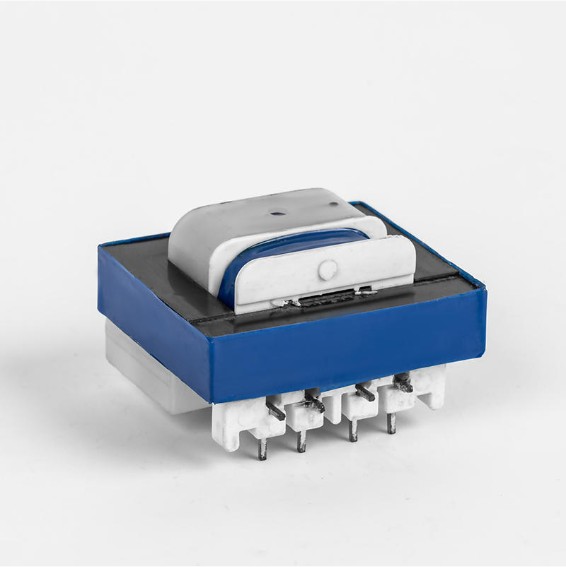
High frequency transformers are the enabling component in switch-mode power supplies (SMPS), where mains AC is first rectified to DC, then switched at high frequency (typically 20 kHz–300 kHz) before being fed into the transformer. Operating at higher frequency means the core can be dramatically smaller for the same power rating. A 65W laptop charger using high frequency transformation fits in the palm of your hand; an equivalent 50 Hz transformer would be brick-sized. High frequency designs are essential in telecom power supplies, medical imaging equipment, EV on-board chargers, and LED drivers where compactness is critical.
Key Applications of Transformers Across Industries
Power Transmission and Distribution
Electrical energy is generated at power plants at voltages typically between 11 kV and 25 kV. Step-up transformers raise this to 220 kV, 400 kV, or even 765 kV for long-distance transmission, dramatically reducing resistive losses (power loss = I²R, so doubling the voltage and halving the current reduces losses by 75%). At the destination, step-down transformers progressively reduce voltage to 33 kV, 11 kV, and finally 230/400 V for end users.
Industrial Welding and Manufacturing
Electric arc welders depend on low frequency transformers to convert mains voltage (230 V or 400 V) down to the low voltages (20–80 V) required for welding arcs, while delivering very high currents — typically 100–500 A or more. The transformer's inherent leakage inductance provides a natural current-limiting characteristic that stabilizes the welding arc, which is essential for consistent weld quality in industrial manufacturing.
Renewable Energy: Photovoltaic Inverters and Energy Storage
In photovoltaic (PV) systems, low frequency transformers within string or central inverters convert the processed DC from solar panels into grid-compatible AC, while providing the galvanic isolation required by many grid standards. In battery energy storage systems (BESS), bidirectional transformers handle both charging (AC→DC) and discharging (DC→AC) cycles. Global installed solar capacity surpassed 1.6 TW in 2024, representing enormous and growing demand for reliable transformer technology in this sector.
Home Appliances and Lighting
Transformers in air conditioners convert AC to DC for variable-speed compressor drives and fan motors. In lighting systems, transformers — including electronic ballasts with high frequency transformers — regulate voltage and current to fluorescent and LED fixtures. Low frequency isolation transformers in HVAC and refrigeration systems protect sensitive control electronics from power line disturbances, ensuring stable and efficient cooling or heating operation across varying grid conditions.
Transformer Drawbacks and Limitations
Despite their advantages, transformers have real limitations that engineers must account for during system design:
- AC-only operation: Conventional transformers only work with alternating current. DC voltages cannot be transformed without first being inverted to AC — which is why DC-based systems require inverters or converters incorporating high frequency transformers.
- Size and weight at low frequency: Low frequency operation demands larger cores and more copper winding. A 10 kVA, 50 Hz transformer may weigh 50–80 kg, which is impractical in space-constrained or portable environments.
- No-load core losses: Hysteresis and eddy current losses occur whenever the transformer is energized, even at zero load. A large distribution transformer running at 10% load still incurs 100% of its no-load losses, reducing efficiency in lightly loaded networks.
- Harmonic distortion sensitivity: Non-linear loads (VFDs, UPS rectifiers, EV chargers) inject harmonic currents into transformer windings, causing additional heating and accelerated aging. Without K-factor rated designs, a standard transformer may need to be derated to 50–70% of nameplate capacity under heavy harmonic loads.
- Inrush current at energization: When first switched on, transformers can draw inrush currents of 8–12 times rated current for several cycles, requiring properly calibrated protection relays to prevent nuisance tripping.
- Environmental concerns (oil-filled types): Mineral oil-filled transformers carry fire and spill risks. This is driving growing adoption of dry-type and biodegradable natural ester fluid designs, especially for indoor, underground, and environmentally sensitive installations.
Conclusion: Choosing the Right Transformer for Your Application
Transformers — whether low frequency or high frequency — remain irreplaceable in modern electrical systems. The right choice depends on your specific operating requirements:
- If you need high power, robust electrical isolation, surge tolerance, and direct grid-frequency operation — for power distribution, industrial welding, solar inverters, HVAC, or energy storage — a low frequency transformer is the appropriate choice.
- If you need compact size, lightweight packaging, and integration into switched-mode circuits — for laptop chargers, telecom power, medical devices, or EV on-board chargers — high frequency transformers are the optimal solution.
As energy systems evolve — driven by expanding renewable generation, distributed battery storage, and EV infrastructure — the demand for high-performance transformers is accelerating. Advances in amorphous and nanocrystalline core materials, improved insulation systems, and smart monitoring (IoT-enabled transformers with real-time load, temperature, and health diagnostics) are pushing efficiency and reliability to new heights. Understanding how transformers work is not merely academic: it is foundational knowledge for designing, specifying, and maintaining the electrical systems that power modern industry and daily life.


Welcome To CHUANGBIAO
Address : No.420-3, Sanbei East Road, Guanhaiwei Industrial Zone, Cixi City, Ningbo, Zhejiang, China
Contact
- Tel: +86 186 6825 0703
- Email: linjian@nbcbdz.com
About us
Products
Copyright © Ningbo Chuangbiao Electronic Technology Co., Ltd.
All Rights Reserved. EI Transformer Manufacturer


