
 English
 中文简体
中文简体Transformer Basics:What is transformer?
2026-03-06
Content
- 1 The Transformer and the Principles of Electromagnetic Induction
- 2 Single Phase Voltage Transformer
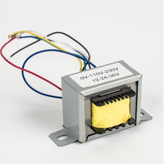
- 3 Transformer Construction (Single-Phase)
- 4 A Transformer's Turns Ratio
- 5 Transformer Action Explained
- 6 Transformer Basics Example: Worked Calculation
- 7 Electrical Power in a Transformer
- 8 Transformer Efficiency
- 9 Transformer Efficiency Triangle
- 10 Transformer Basics Summary
- 11 Basic Representation of the Transformer
A transformer is a static electrical device that transfers electrical energy between two or more circuits through electromagnetic induction, without any direct electrical connection. Its core function is to step voltage up or down while keeping power (ideally) constant. Understanding transformer basics is essential for anyone working with power systems, industrial controls, or renewable energy applications.
In practice, a transformer connected to a 240V primary supply with a turns ratio of 10:1 will deliver approximately 24V at the secondary — a straightforward relationship that underpins all transformer design and selection.
The Transformer and the Principles of Electromagnetic Induction
Transformers operate entirely on Faraday's Law of Electromagnetic Induction. When an alternating current flows through the primary winding, it creates a continuously changing magnetic flux in the core. This changing flux induces an electromotive force (EMF) in the secondary winding.
The induced EMF in each winding is described by:
E = 4.44 × f × N × Φmax
Where:
- f = supply frequency (Hz)
- N = number of turns in the winding
- Φmax = maximum magnetic flux (Webers)
Because transformers rely on changing flux, they only function with alternating current (AC). Applying DC results in no induction — only a resistive voltage drop and potentially damaging heat buildup in the winding.
Single Phase Voltage Transformer

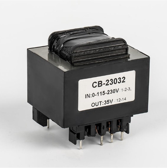
The single-phase voltage transformer is the most fundamental transformer type. It consists of two coils — the primary and the secondary — wound around a shared magnetic core. When an AC voltage is applied to the primary, a proportional voltage appears at the secondary terminals.
Key characteristics of single-phase transformers include:
- Voltage transformation is directly proportional to the turns ratio
- Current transformation is inversely proportional to the turns ratio
- The primary and secondary are electrically isolated but magnetically coupled
- Common applications include household appliances, industrial controls, and lighting systems
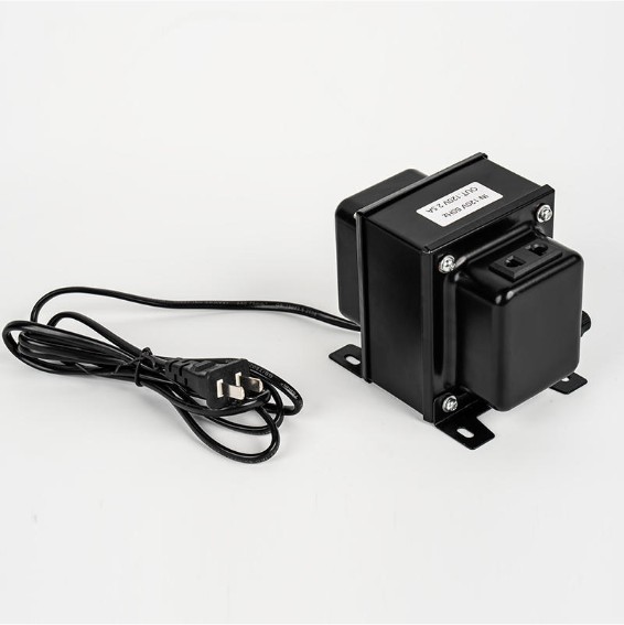
A typical single-phase distribution transformer for residential use steps down the utility supply from 11kV to 230V for safe domestic consumption.
Transformer Construction (Single-Phase)
A single-phase transformer has three primary physical components:
Magnetic Core
The core provides a low-reluctance path for the magnetic flux. It is constructed from thin laminations of silicon steel (typically 0.35mm to 0.5mm thick), each coated with insulating varnish. This laminated structure reduces eddy current losses by up to 90% compared to a solid core of the same dimensions.
Two common core configurations are used:
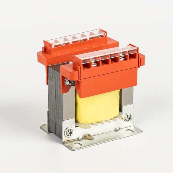
- Core-type: Windings surround the core limbs; better for high-voltage applications
- Shell-type: Core surrounds the windings; offers better magnetic shielding and is compact
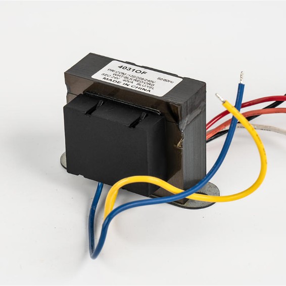
Windings
Windings are made from copper or aluminum conductors insulated with enamel or paper. The primary winding is connected to the input supply; the secondary winding delivers power to the load. Conductors are sized based on the current they carry — the higher-voltage winding typically has more turns of thinner wire, while the lower-voltage winding uses fewer turns of thicker wire.
Insulation System
Insulation separates the primary and secondary windings and isolates each from the core. Common insulating materials include Kraft paper, pressboard, and varnished cambric. The insulation class (e.g., Class B at 130°C, Class F at 155°C) determines the maximum operating temperature.
A Transformer's Turns Ratio
The turns ratio is the single most important parameter in transformer design. It defines the relationship between primary and secondary voltages and currents.
Turns Ratio (a) = NP / NS = VP / VS = IS / IP
Where NP and NS are the number of turns on the primary and secondary respectively, VP and VS are the corresponding voltages, and IP and IS are the currents.
| Turns Ratio (NP:NS) | Primary Voltage | Secondary Voltage | Transformer Type |
|---|---|---|---|
| 10:1 | 240V | 24V | Step-Down |
| 1:10 | 240V | 2400V | Step-Up |
| 1:1 | 240V | 240V | Isolation |
| 5:1 | 120V | 24V | Step-Down |
Note that while voltage scales with the turns ratio, current scales inversely — a transformer that halves the voltage will double the current (assuming an ideal transformer).
Transformer Action Explained
Transformer action refers to the full sequence of energy transfer from primary to secondary. Here is the step-by-step process:
- AC voltage is applied to the primary winding, driving an alternating current through it.
- This current establishes an alternating magnetic flux in the core, completing typically 50 or 60 full cycles per second depending on the supply frequency.
- The changing flux links with the secondary winding and induces a voltage (by Faraday's Law).
- When a load is connected to the secondary, current flows, and the load receives power.
- The secondary current creates its own flux that opposes the primary flux (Lenz's Law), causing the primary to draw more current from the supply to compensate — a self-regulating mechanism.
This action is entirely contactless — no moving parts, no electrical connection between windings — making transformers exceptionally reliable with lifespans often exceeding 25–40 years in well-maintained installations.
Transformer Basics Example: Worked Calculation
Consider a single-phase transformer with the following specifications:
- Primary voltage (VP): 230V
- Secondary voltage (VS): 12V
- Primary turns (NP): 1150 turns
- Load resistance: 10Ω
Step 1 — Find the turns ratio: a = 230 / 12 ≈ 19.17
Step 2 — Find NS: NS = NP / a = 1150 / 19.17 ≈ 60 turns
Step 3 — Find secondary current: IS = VS / R = 12 / 10 = 1.2A
Step 4 — Find primary current (ideal): IP = IS / a = 1.2 / 19.17 ≈ 0.063A (63mA)
This example illustrates how the primary draws only a small current while delivering 12V to the load — a practical demonstration of voltage step-down with current step-up.
Electrical Power in a Transformer
In an ideal transformer, input power equals output power. There is no energy conversion — only energy transfer:
Pin = VP × IP = VS × IS = Pout
In the real world, a portion of the input power is lost. These losses fall into two categories:
Core (Iron) Losses
Core losses are constant regardless of load and consist of:
- Hysteresis loss: Energy dissipated as the magnetic domains in the core reverse direction each cycle. Reduced by using grain-oriented silicon steel.
- Eddy current loss: Circulating currents induced within the core material. Reduced by laminating the core.
Copper (I²R) Losses
Copper losses arise from the resistance of the winding conductors and vary with the square of the load current: PCu = I² × R. These losses increase significantly at higher loads, which is why transformers are rated at a specific kVA to prevent overheating.
Transformer Efficiency
Transformer efficiency (η) is defined as the ratio of output power to input power, expressed as a percentage:
η (%) = (Pout / Pin) × 100 = (Pout / (Pout + Plosses)) × 100
Modern power transformers routinely achieve efficiencies of 97% to 99.5%, making them among the most efficient electrical devices ever engineered. A 100 kVA transformer at 99% efficiency dissipates only about 1 kW as heat while delivering 99 kW of usable power.
Maximum efficiency occurs when copper losses equal iron losses — a condition that can be engineered by careful selection of core material, core cross-section, and conductor sizing. For a transformer rated 50 kVA with iron losses of 200W and copper losses of 200W at full load:
η = 50,000 / (50,000 + 200 + 200) × 100 = 99.2%
Transformer Efficiency Triangle
The efficiency triangle is a visual tool derived from the power triangle, useful for understanding the relationship between input power, output power, and losses in a transformer.
The three sides represent:
- Input power (Pin): The hypotenuse — total energy drawn from the supply
- Output power (Pout): Useful power delivered to the load
- Losses (Ploss): Core losses + copper losses dissipated as heat
The efficiency angle θ represents how close the transformer operates to ideal — a smaller angle indicates higher efficiency. This conceptual model helps engineers visualize efficiency trade-offs when optimizing transformer design for specific load profiles.
Transformer Basics Summary
The key principles of transformer operation can be summarized as follows:
| Parameter | Relationship | Notes |
|---|---|---|
| Voltage | VP/VS = NP/NS | Directly proportional to turns |
| Current | IP/IS = NS/NP | Inversely proportional to turns |
| Power (ideal) | Pin = Pout | No energy conversion, only transfer |
| Efficiency | η = Pout/Pin × 100% | Typically 97%–99.5% for power transformers |
| Core losses | Hysteresis + eddy current | Constant; independent of load |
| Copper losses | P = I²R | Variable; proportional to load² |
Basic Representation of the Transformer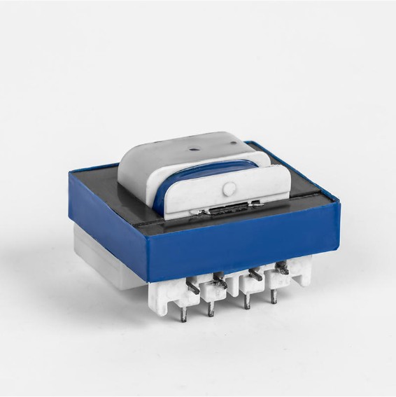
In circuit diagrams and engineering schematics, the transformer is represented by two coupled coil symbols separated by vertical lines (representing the core). The standard schematic conveys:
- Dot notation: Dots at one terminal of each winding indicate the polarity — voltages at dotted terminals are in phase
- Core lines: Single lines represent an air-core transformer; double lines represent an iron-core transformer
- Winding labels: Primary (left) and secondary (right) are clearly differentiated
For an ideal transformer model used in circuit analysis, the equivalent circuit includes an ideal transformer with turns ratio a, representing perfect energy transfer. Real transformer models add series resistance (R1, R2) and leakage reactance (X1, X2) for each winding, plus a shunt branch representing the magnetizing reactance and core loss resistance — giving engineers a complete tool for predicting voltage regulation and efficiency under any load condition.
Voltage regulation — the change in secondary terminal voltage from no-load to full-load — is a key performance metric. A well-designed low-frequency transformer maintains voltage regulation within 2% to 5%, ensuring stable voltage delivery across the entire load range.
Whether used in a 230V household supply, a 10kV industrial substation, or a photovoltaic inverter converting solar DC to grid AC, the transformer remains the foundational device of electrical power engineering — simple in principle, extraordinary in application.


Welcome To CHUANGBIAO
Address : No.420-3, Sanbei East Road, Guanhaiwei Industrial Zone, Cixi City, Ningbo, Zhejiang, China
Contact
- Tel: +86 186 6825 0703
- Email: linjian@nbcbdz.com
About us
Products
Copyright © Ningbo Chuangbiao Electronic Technology Co., Ltd.
All Rights Reserved. EI Transformer Manufacturer


