
 English
 中文简体
中文简体What causes low frequency transformer overheating?
2026-07-31
Content
A low frequency transformer overheats mainly because of sustained electrical overload, magnetic core saturation, harmonic-rich loads, restricted airflow around the winding, and aging or substandard insulation. In most field cases, temperature rise above the rated class is not caused by one single fault, but by two or three of these factors acting together — for example, a slightly oversized load combined with a cabinet that traps hot air. Identifying which factor dominates is the first step to solving the problem, and it usually takes less than an hour with a clamp meter and an infrared thermometer.
Six Conditions That Push Temperature Above the Rated Class
Every low frequency transformer, whether it is a standard EI transformer, a square transformer, or a toroidal transformer, is designed around an insulation class with a fixed temperature margin. Once operating conditions exceed that margin, the winding insulation ages faster and copper losses climb in a self-reinforcing cycle.
01
Continuous Overload
Running a unit at 115 to 130 percent of its rated kVA for long periods raises copper loss roughly with the square of the current, so a 20 percent overload can add 44 percent more heat than the design allows.
02
Core Saturation
Applying voltage above the nameplate rating, or connecting the transformer to an unstable low frequency inverter output, drives the EI or square core into saturation, causing sharp increases in magnetizing current and core loss.
03
Harmonic Distortion
Non-linear loads such as variable frequency drives, rectifiers, and switching power supplies feed harmonic currents back into the winding, generating extra eddy-current and stray losses that a standard load calculation does not capture.
04
Restricted Ventilation
Enclosed cabinets, dust buildup on the windings, or mounting a control transformer too close to other heat-generating components can raise the surrounding air temperature by 10 to 15 degrees Celsius before it even reaches the coil.
05
High Ambient Temperature
Every rated temperature rise assumes a 40 degree Celsius ambient. Operating in a 50 degree environment without derating the load effectively removes most of the transformer's thermal safety margin.
06
Insulation Aging or Defects
Loose windings, uneven varnish impregnation, or moisture absorbed during storage lower the breakdown resistance of the insulation, so heat that used to be tolerated now accelerates degradation and can lead to internal short circuits.
How Overload and Harmonics Compare in Practice
The table below shows typical outcomes recorded during load testing of low frequency transformer units at similar ambient conditions. These figures illustrate why even a moderate overload combined with harmonic distortion is more damaging than either factor alone.
| Operating Condition | Approx. Temperature Rise Above Rated | Estimated Insulation Life Impact |
| Rated load, clean sine wave | 0 to 5 percent | Normal service life |
| 15 percent overload only | 10 to 18 percent | Life reduced by roughly 30 to 40 percent |
| Rated load with 20 percent THD | 12 to 20 percent | Life reduced by roughly 35 to 45 percent |
| Overload plus harmonics plus poor ventilation | 25 percent or more | Life reduced by over 60 percent, early failure likely |
Core Structure Changes the Heat Pattern
Not every transformer heats up the same way, and the winding geometry has a direct effect on how quickly heat is generated and how easily it escapes.
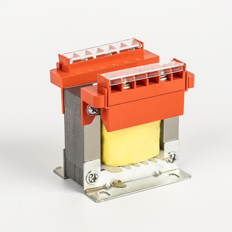
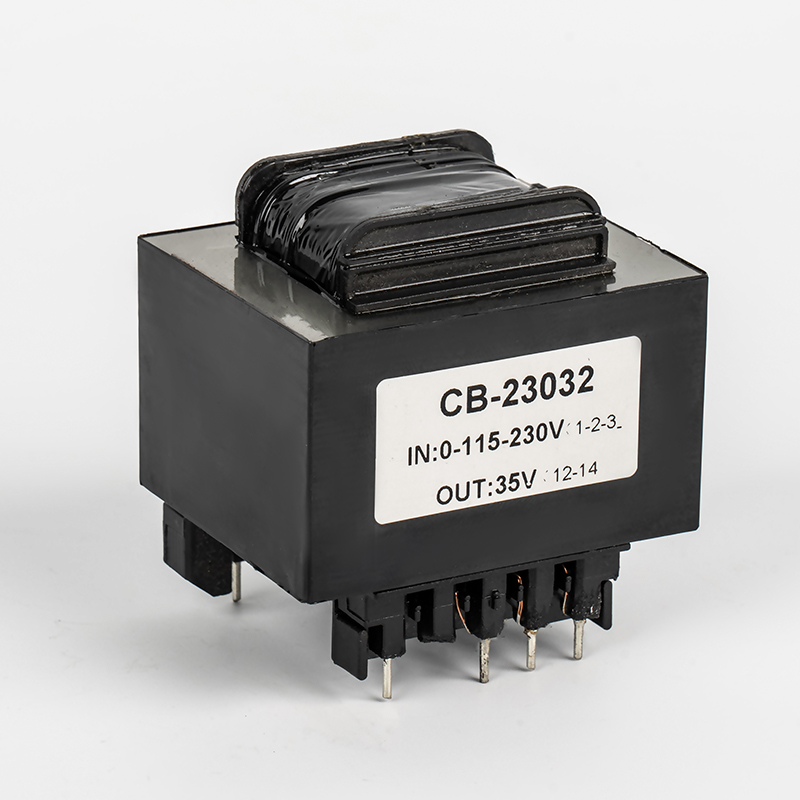
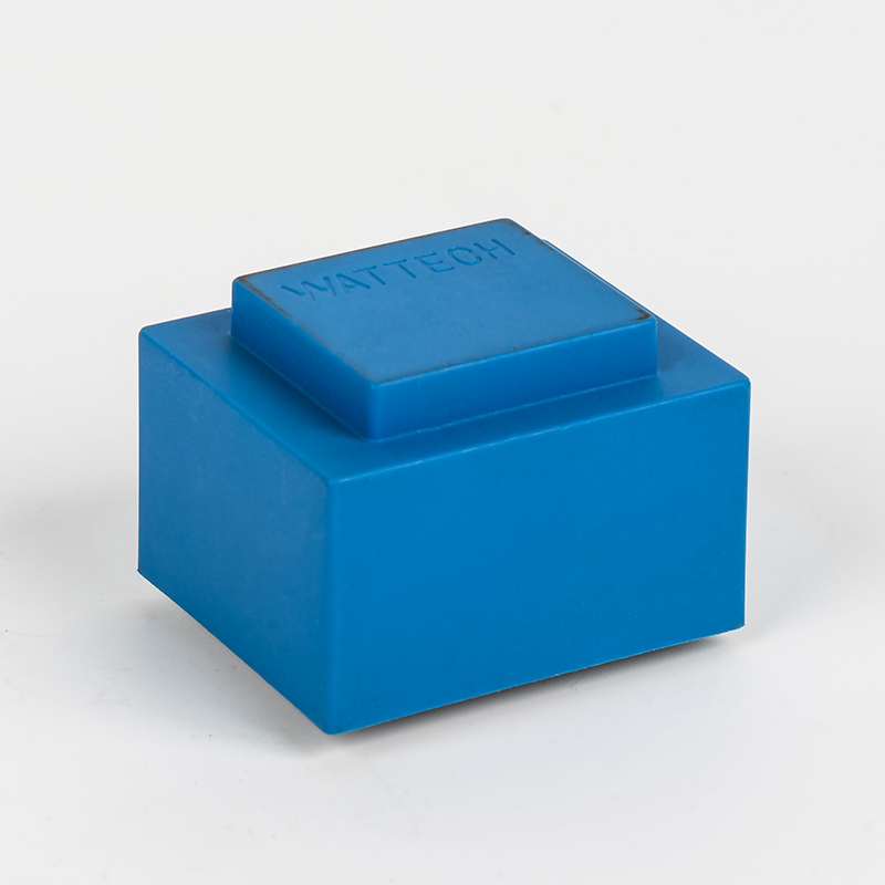
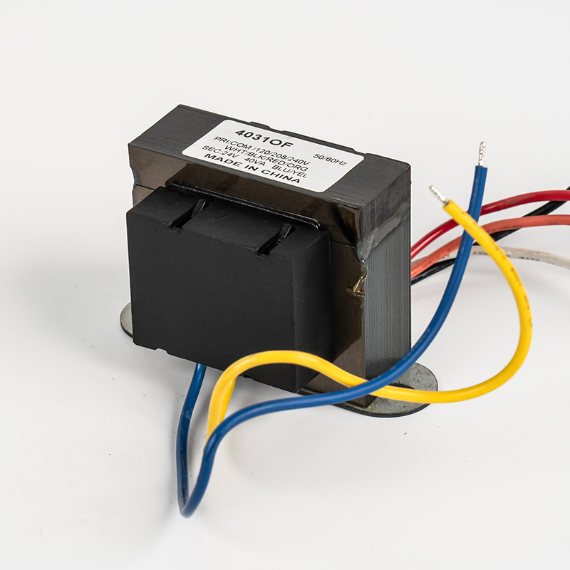
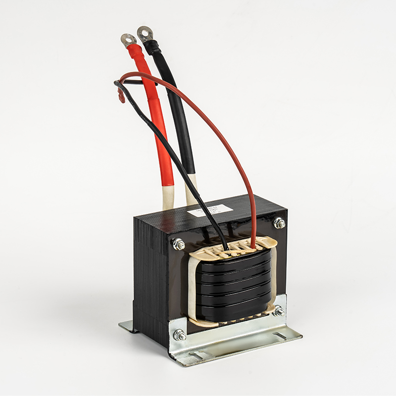
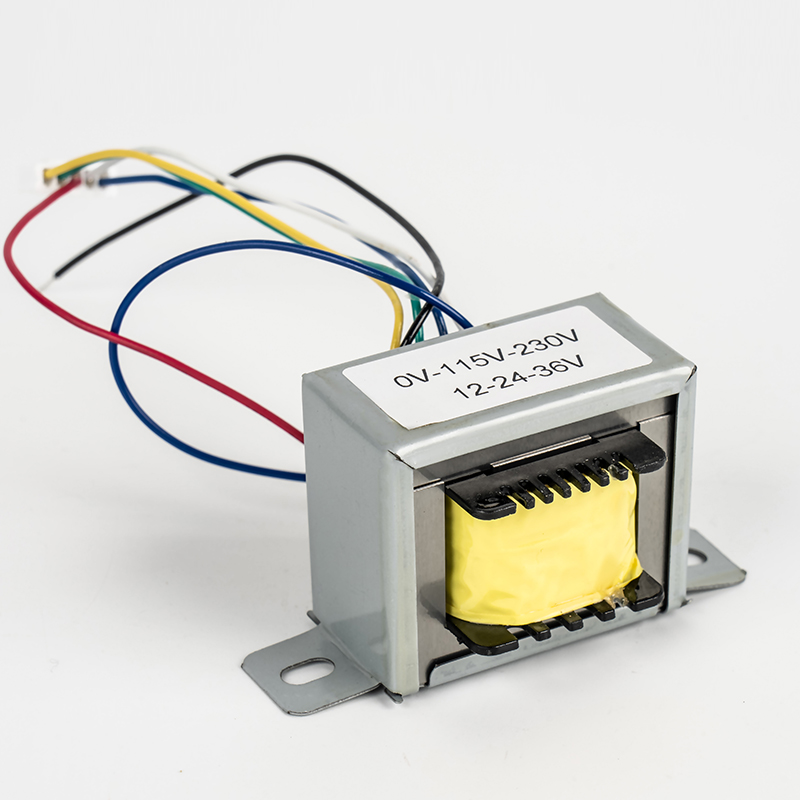
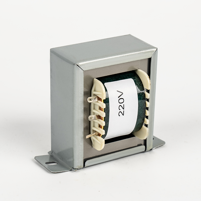
An EI transformer uses a laminated E and I core with a rectangular winding window. This structure is rugged and cost effective, but the corner areas of the winding tend to run hotter than the center because of longer flux paths and reduced airflow. A square transformer follows a similar principle with a more compact frame, which improves power density but requires more attention to ventilation spacing since the surface area available for heat dissipation is smaller relative to its output.
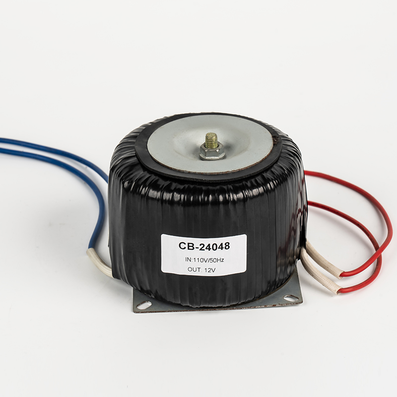
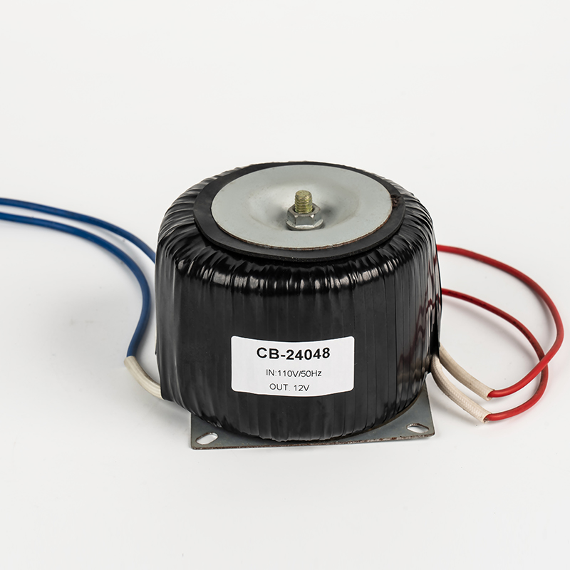
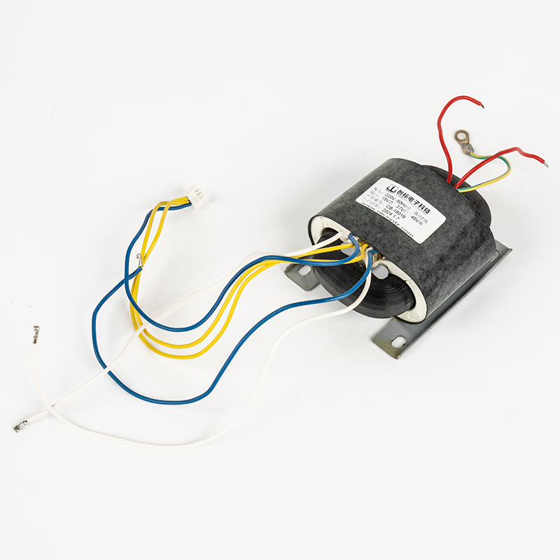
A toroidal transformer, by contrast, wraps the winding evenly around a ring-shaped core. This produces a shorter magnetic path, lower no-load loss, and a more uniform temperature distribution across the coil. For this reason, a toroidal inverter transformer or a toroid isolation transformer generally runs several degrees cooler than an EI unit of the same rating under identical load, which is one reason toroidal designs are favored in noise-sensitive or space-constrained equipment.
Related Low Frequency Transformer Types
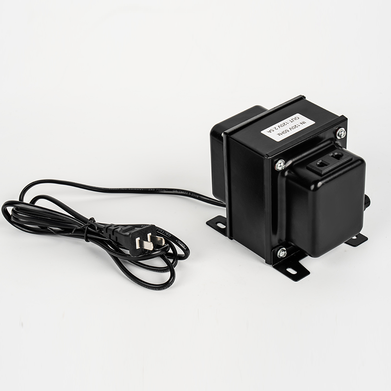
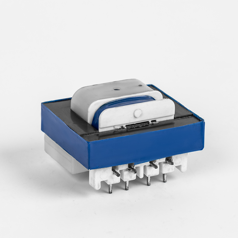
Different applications call for different winding structures and cooling behavior. The five types below are commonly compared when diagnosing or preventing overheating issues.
Cooling and Ventilation Requirements by Application
Because control transformer and isolation transformer units are frequently mounted inside enclosed panels, cooling clearance matters as much as electrical sizing. A few practical guidelines apply across most low frequency transformer installations:
- Leave at least 25 to 30 millimeters of open air space around all sides of the transformer body, and more if it shares a cabinet with drives or rectifiers.
- Avoid mounting a low frequency transformer directly above another heat source; hot air rising from below adds directly to the coil temperature.
- Clean dust from ventilation slots on open-frame units every six to twelve months, since dust acts as a thermal blanket that traps heat inside the winding.
- For a BK transformer or other panel-mount control transformer feeding intermittent loads, confirm the duty cycle rating matches the actual on-time of the connected equipment rather than only the peak current.
- When ambient temperature regularly exceeds 40 degrees Celsius, apply a derating factor of about 1.5 percent per additional degree, or select a unit from a higher insulation class.
Warning Signs to Check Before a Failure Occurs
| Observation | Likely Cause | Recommended Action |
| Discoloration or a burning smell near the windings | Sustained overheating, insulation breakdown starting | Remove from service and inspect insulation resistance immediately |
| Humming louder than usual | Core saturation or loose laminations | Check input voltage and mounting hardware |
| Case temperature noticeably higher on one side | Airflow blockage or uneven winding load | Improve clearance, redistribute connected loads |
| Frequent nuisance tripping of thermal protection | Marginal overload or harmonic-rich load | Re-measure true RMS current and consider upsizing kVA rating |
Preventive Measures That Extend Service Life
Working with an established low-frequency transformer factory helps at the design stage, since correct core sizing, wire gauge, and insulation class selection prevent most overheating problems before installation. As a long-term EI transformer factory and square transformer factory, production teams typically size the core with a safety margin above the calculated load, use class F or class H insulation for demanding environments, and verify temperature rise through load testing before shipment.
On the user side, three habits make the biggest difference: matching the transformer rating to the actual load profile rather than only the nameplate current of connected equipment, scheduling a thermal check with an infrared camera at least once a year, and keeping firmware or drive settings on connected inverters within the voltage range the transformer was designed for. For facilities running mixed equipment, sourcing both low frequency units and a high frequency transformer factory product line from the same supplier also simplifies maintenance, since testing procedures and spare part specifications stay consistent across the plant.
Addressing these factors together, rather than replacing a transformer reactively after each failure, is the most reliable way to keep operating temperatures within the rated class and extend service life well beyond the standard warranty period.


Welcome To CHUANGBIAO
Address : No.420-3, Sanbei East Road, Guanhaiwei Industrial Zone, Cixi City, Ningbo, Zhejiang, China
Contact
- Tel: +86 186 6825 0703
- Email: linjian@nbcbdz.com
About us
Products
Copyright © Ningbo Chuangbiao Electronic Technology Co., Ltd.
All Rights Reserved. EI Transformer Manufacturer


