
 English
 中文简体
中文简体What are the types of Transformer?
2026-04-03
Content
- 1 Transformer Basics: What Every Engineer Must Know First
- 2 Transformer Construction: Core Materials, Windings & Insulation
- 3 Types of Transformers: A Practical Classification
- 4 Transformer Loading: How Load Affects Performance
- 5 Multiple Winding Transformers: Flexibility in Power Distribution
- 6 The Step-Up Transformer: Compact & Efficient Voltage Conversion
- 7 The High Current Transformer: Precision Measurement & Protection
- 8 Inverter Transformers: The Backbone of Power Conversion Systems
- 9 R-Type Transformers: Precision Coupling for Sound Quality
- 10 Transformer Voltage Regulation: Maintaining Stable Output Under Load
- 11 Frequently Asked Questions
- 12 Ningbo Chuangbiao Electronic Technology
Section 01
Transformer Basics: What Every Engineer Must Know First
At its core, a transformer operates on Faraday’s Law of Electromagnetic Induction: a changing magnetic flux in a coil induces a voltage proportional to the rate of change and the number of turns. When AC voltage is applied to the primary winding, it creates a time-varying flux in the core, which then induces a voltage in the secondary winding.
The fundamental voltage relationship is governed by the turns ratio:
V₁ / V₂ = N₁ / N₂
For example, a transformer with a 10:1 turns ratio steps down 220V to 22V. Similarly, current transforms inversely: I₁ / I₂ = N₂ / N₁, ensuring power (V × I) remains nearly constant across both windings (minus losses).
Key Parameters at a Glance
| Parameter | Formula / Typical Value | Significance |
|---|---|---|
| Turns Ratio (a) | N₁ / N₂ | Determines voltage step-up or step-down |
| Efficiency (η) | 95–99% (power transformers) | Ratio of output to input power |
| Operating Frequency | 50/60 Hz (power), up to MHz (HF) | Affects core material selection |
| Regulation | Typically 2–10% | Voltage stability under load changes |
Section 02
Transformer Construction: Core Materials, Windings & Insulation
The physical construction of a transformer directly determines its efficiency, power rating, frequency response, and thermal performance. Three main elements define any transformer’s construction.
The Magnetic Core
Silicon Steel
Used at 50/60 Hz. High permeability & low core loss.
Amorphous Metal
Reduces core losses by 70–80% vs silicon steel.
Ferrite
High-frequency (kHz–MHz) SMPS and audio stages.
Powdered Iron
RF and filter inductors with distributed air gaps.
Windings
Copper is preferred for its lower resistivity (1.68 × 10⁻⁸ Ω·m vs. aluminum’s 2.82 × 10⁻⁸ Ω·m), yielding smaller, lighter transformers for the same power rating.
Insulation Classes
| Insulation Class | Max Temperature | Typical Materials |
|---|---|---|
| Class A | 105°C | Cotton, paper, varnish |
| Class B | 130°C | Mica, glass fiber |
| Class F | 155°C | Synthetic resins |
| Class H | 180°C | Silicone, glass fiber composites |
Section 03
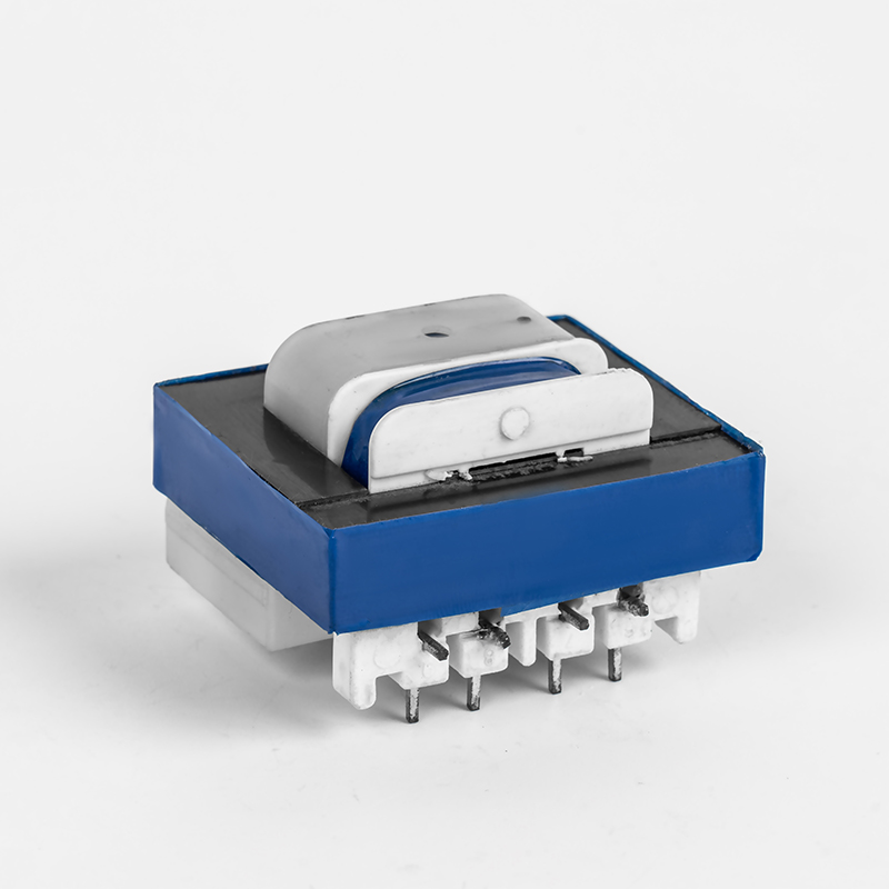
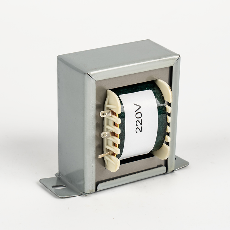
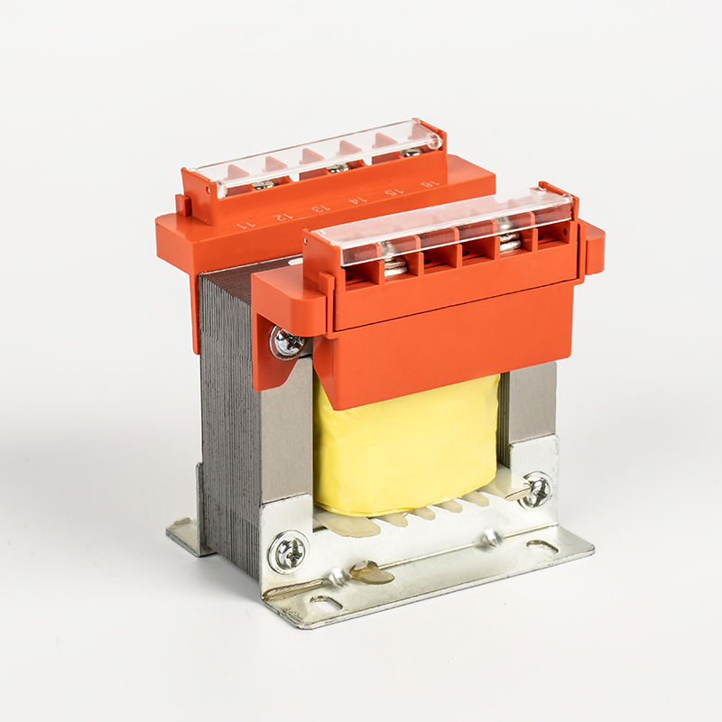
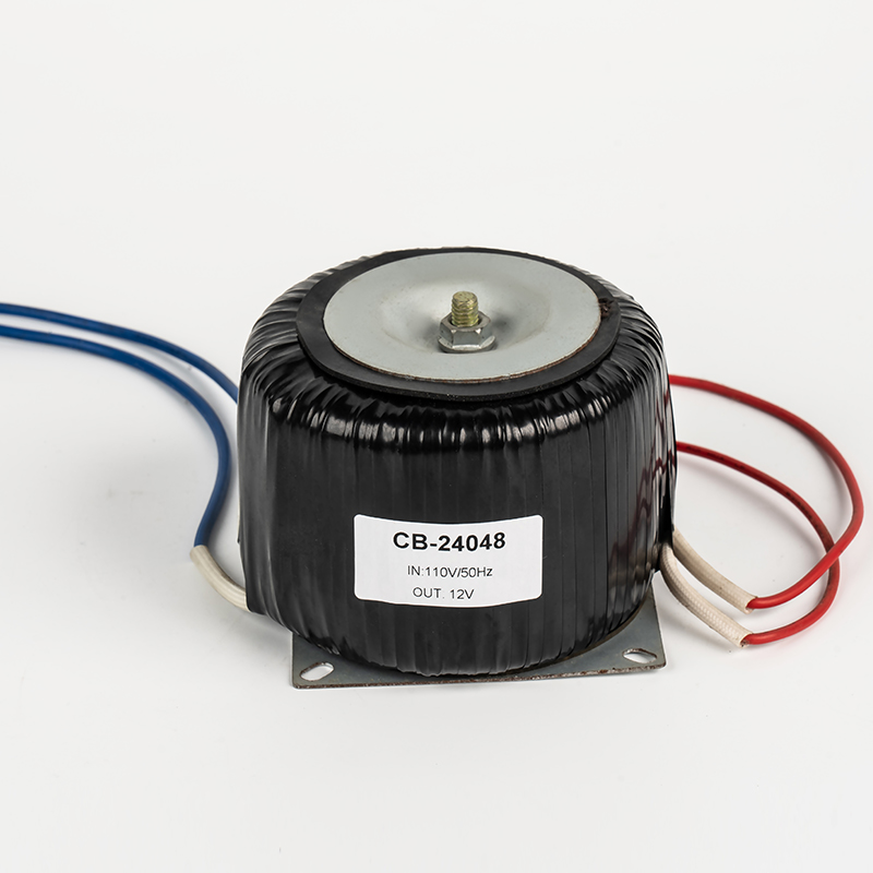
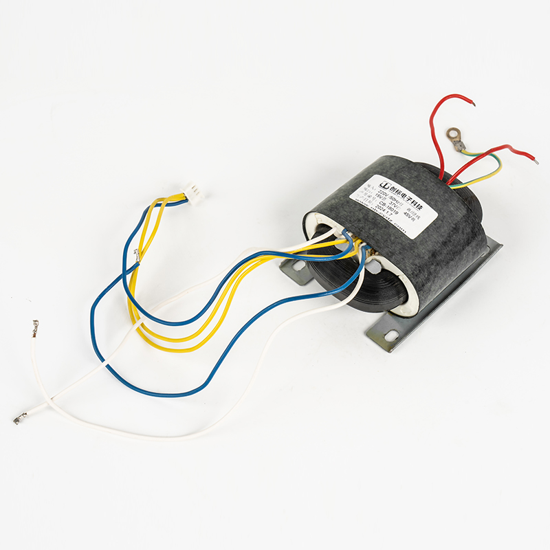
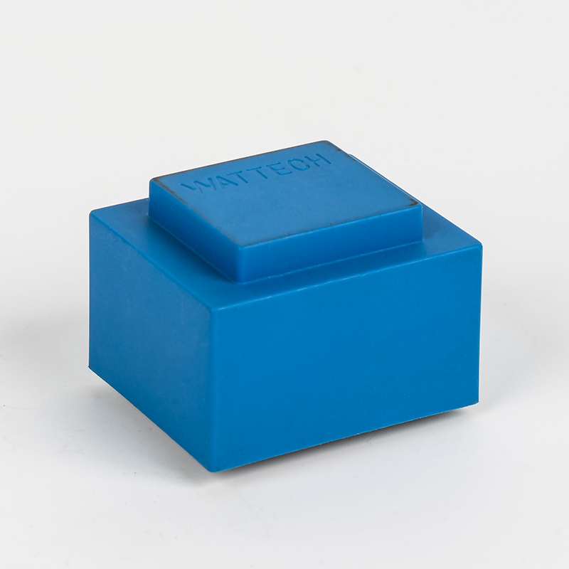
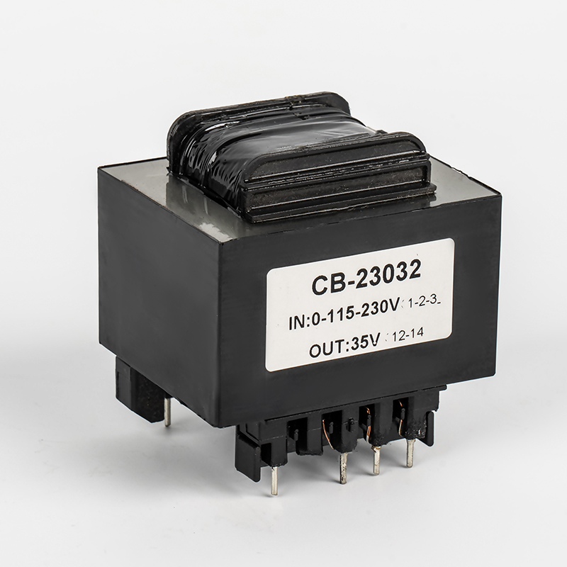
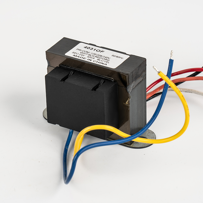
Types of Transformers: A Practical Classification
Transformers are classified by function, core shape, application, and winding configuration. Ningbo Chuangbiao manufactures the full spectrum of types shown below, each tailored to its application domain.
Section 04
Transformer Loading: How Load Affects Performance
Transformer loading refers to the relationship between the connected load and the transformer’s rated capacity. Operating at 75–85% of rated kVA is generally considered optimal, balancing efficiency against thermal margin.
No-Load vs. Full-Load Conditions
Under no-load, only the magnetizing current flows, causing core losses (hysteresis + eddy currents), typically 0.5–1.5% of rated power for modern silicon steel cores.
Under full load, copper losses (I²R in the windings) dominate. A transformer at 50% load incurs only 25% of the full-load copper losses.
Overloading Risks
Thermal Rule: Every 10°C rise approximately halves insulation lifetime (Arrhenius rule).
Continuous overload at 120% rated load can reduce a Class B transformer’s service life from 20 years to under 5 years.
A transformer rated at 10 kVA supplying a load at 0.8 power factor delivers only 8 kW of real power. Industrial installations often use power factor correction capacitors to reduce this burden.
Section 05
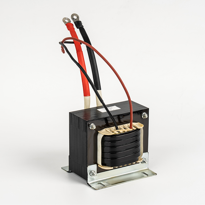
Multiple Winding Transformers: Flexibility in Power Distribution
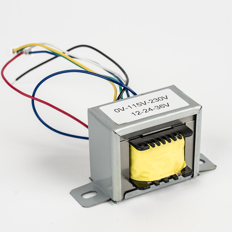
Multiple winding transformers feature one primary and two or more secondary windings on a common core, allowing a single unit to supply multiple independent voltages simultaneously.
Center-tapped secondary
Provides both full and half-voltage outputs. A 0–12–24V secondary delivers 24V across the full winding and 12V from either end to the center. Widely used in full-wave rectifier circuits.
Multiple isolated secondaries
Entirely separate windings allow different voltages for different circuits—e.g., +15V for op-amps, +5V for logic, and 12V for relays from one transformer.
Series / parallel connection
Secondary windings connected in series add voltages; in parallel, they add current capacity. The primary must be rated for the sum of all secondary VA loads plus efficiency losses.
Section 06
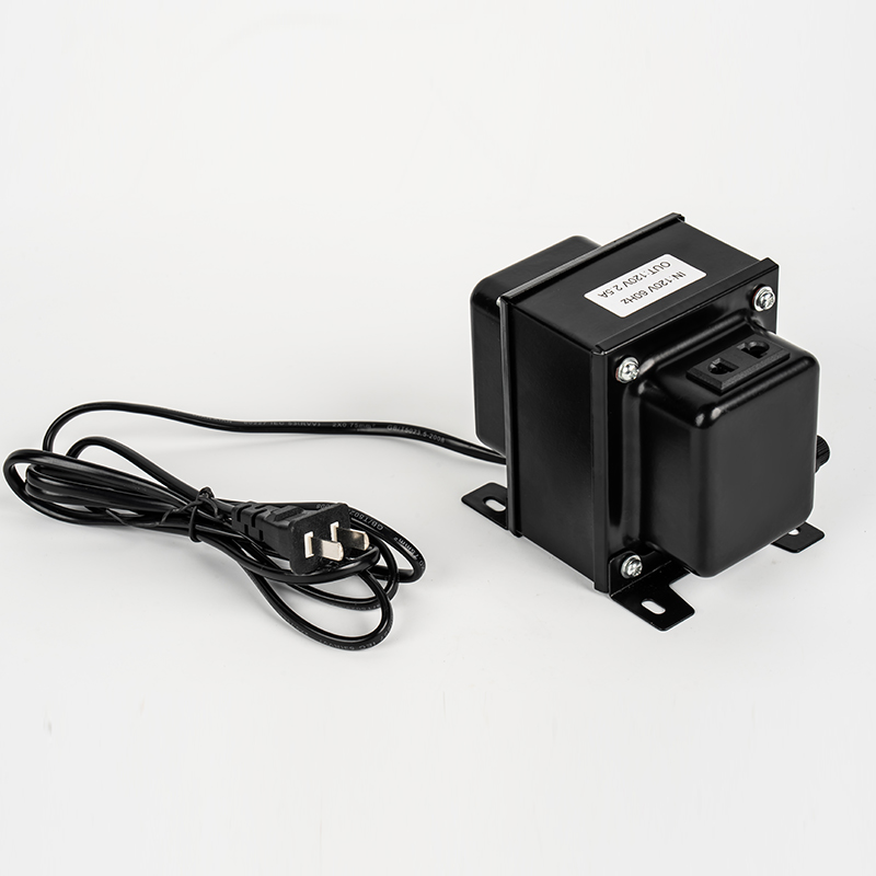
The Step-Up Transformer: Compact & Efficient Voltage Conversion
A step-up transformer increases voltage from primary to secondary (N₂ > N₁). For a step-down from 240V to 200V, the internal winding handles only the voltage difference (40V), making it approximately 5× smaller than an equivalent isolation transformer.
>98%
Typical Efficiency
5×
Smaller Footprint
When NOT to Use a Step-Up Approach
Medical equipment: Galvanic isolation is mandatory per IEC 60601 for patient safety.
Sensitive electronics where high-voltage transients on the primary must not reach the secondary.
Large step ratios (> 2:1 or < 1:2): efficiency gains diminish, and the design becomes impractical.
Section 07
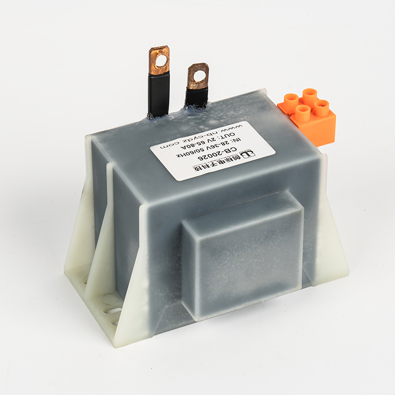
The High Current Transformer: Precision Measurement & Protection
A high current transformer is specifically designed to reproduce a scaled-down replica of a primary current in its secondary circuit, enabling safe measurement of high currents using standard instruments.
Standard Accuracy Classes
| Class | Max Ratio Error | Typical Use |
|---|---|---|
| 0.1 | ±0.1% | Precision laboratory measurement |
| 0.5 | ±0.5% | Revenue-grade energy metering |
| 1.0 | ±1.0% | General industrial metering |
| 5P / 10P | ±1–3% | Protection relays |
Critical Safety Rule: Never open-circuit the secondary of an operating current transformer. Without a burden, primary current becomes purely magnetizing, driving the core into saturation and producing voltage spikes of potentially thousands of volts—destroying insulation and endangering personnel.
Section 08
Inverter Transformers: The Backbone of Power Conversion Systems
Inverter transformers are fundamental to modern energy systems—solar inverters, UPS equipment, and industrial motor drives all rely on them. A three-phase inverter transformer is more economical than three single-phase units of equivalent rating—typically 15–20% lighter and cheaper.
Winding Connection Configurations
| Configuration | Symbol | Phase Shift | Application |
|---|---|---|---|
| Star–Star | Yy0 | 0° | HV transmission |
| Star–Delta | Yd1/Yd11 | 30° | Distribution step-down |
| Delta–Star | Dy1/Dy11 | 30° | Generator step-up |
| Delta–Delta | Dd0 | 0° | Industrial drive systems |
Section 09
R-Type Transformers: Precision Coupling for Sound Quality
R-type and audio transformers are engineered for signal frequencies from 20 Hz to 20 kHz, demanding exceptional flatness of frequency response, extremely low distortion, and high common-mode rejection.
Frequency Response
±0.5 dB
20 Hz – 20 kHz
THD (professional)
<0.01%
at 1 kHz nominal level
Insertion Loss
0.5–1.5 dB
Well-designed units
CMRR
>60 dB
at 1 kHz, balanced line
Applications include microphone input transformers, output transformers for tube amplifiers (matching 2–10 kΩ plate circuits to 4–16 Ω speakers), and DI boxes that prevent ground loops between stage equipment and consoles.
Section 10
Transformer Voltage Regulation: Maintaining Stable Output Under Load
Voltage regulation (VR) quantifies how much the output voltage drops from no-load to full-load, expressed as a percentage of full-load voltage:
VR (%) = [(Vₖℓ − Vᶠℓ) / Vᶠℓ] × 100%
Lower VR% is better. A well-designed power transformer typically achieves 2–5% regulation.
Factors Affecting Voltage Regulation
Winding resistance (R): Causes a resistive voltage drop proportional to load current. Heavier conductors reduce this.
Leakage inductance (X): Produces reactive voltage drop, worsening with frequency and load.
Load power factor: At a lagging power factor, inductive drop adds, worsening regulation. At the leading power factor, regulation can improve (negative regulation).
Practical Example
A 1 kVA transformer with a no-load secondary of 230V and a full-load voltage of 220V has VR = 4.55%. Acceptable for most industrial use; precision power supplies may require <1%, typically achieved through external regulation circuits.
Section 11
Frequently Asked Questions
Can a transformer work on DC power?
No. A transformer requires a time-varying magnetic flux to induce voltage in the secondary. DC produces a constant flux, so no EMF is induced. Applying DC also causes dangerously high current limited only by winding resistance, rapidly overheating, and burning out the windings.
What is the difference between step-up and step-down transformers?
The distinction depends purely on turns ratio. A step-up transformer has more turns on the secondary (N₂ > N₁), increasing voltage. A step-down transformer has fewer secondary turns (N₂ < N₁), reducing voltage. The same physical transformer can serve either function depending on which winding is connected to the source.
Why does a transformer hum?
The characteristic 50/60 Hz hum originates from magnetostriction—core laminations physically expand and contract with each flux cycle. Loose laminations amplify this vibration. Properly designed transformers with tight lamination stacking and vibration-damping mountings minimize audible noise to below 40 dB(A) at rated load.
What is galvanic isolation, and why does it matter?
Galvanic isolation means there is no direct electrical connection between primary and secondary circuits—only magnetic coupling. This prevents dangerous ground loops, eliminates common-mode noise, and in medical applications ensures patient safety by blocking potentially lethal fault currents per IEC 60601 standards.
How do I choose the right VA rating?
Calculate total apparent power: VA = Vₚₕₕₜ × Iₚₕₕₜ (or W / power factor for real-power loads). Add a 20–25% safety margin for inrush currents and future load growth. For example, a 500W load at 0.8 PF requires 625 VA; choose a 750 VA or 1 kVA transformer.
What is inrush current?
Inrush current is the large transient current drawn when a transformer is first energized—typically 8–15× the rated full-load current for the first few cycles. This must be considered when sizing fuses and circuit breakers. Some designs incorporate soft-start circuits to limit inrush to 2–3× rated current.
What certifications should a quality transformer carry?
Look for ISO 9001 (quality management), CQC (China quality certification), UL/CE/TÜV safety marks, and RoHS environmental compliance. Medical transformers additionally require IEC 60601-1 compliance. Ningbo Chuangbiao holds ISO 9001, CQC, and RoHS certifications for its full product range.
© Ningbo Chuangbiao Electronic Technology Co., Ltd. | No.420-3, Sanbei East Road, Guanhaiwei Industrial Zone, Cixi City, Ningbo, Zhejiang, China


Welcome To CHUANGBIAO
Address : No.420-3, Sanbei East Road, Guanhaiwei Industrial Zone, Cixi City, Ningbo, Zhejiang, China
Contact
- Tel: +86 186 6825 0703
- Email: linjian@nbcbdz.com
About us
Products
Copyright © Ningbo Chuangbiao Electronic Technology Co., Ltd.
All Rights Reserved. EI Transformer Manufacturer


