
 English
 中文简体
中文简体What power rating (kVA) transformer does my equipment require?
2026-07-17
Content
- 1 Why kVA Rating Is the First Number You Need
- 2 Step by Step: Calculating the kVA You Need
- 3 Worked Example
- 4 Typical kVA Reference by Equipment Type
- 5 How Transformer Design Affects the kVA You Actually Get
- 6 Safety Margin and Derating Factors
- 7 Common Sizing Mistakes to Avoid
- 8 Working With a Transformer Factory
The transformer kVA rating your equipment requires equals the total connected load (in watts) divided by the power factor, then converted to kilovolt-amperes, multiplied by a safety margin of roughly 1.25. For most single-phase workshop or appliance loads this works out to kVA = (Watts ÷ Power Factor ÷ 1000) x 1.25. A precise figure, however, depends on the load type, the starting current of motors, ambient temperature and how many devices run at the same time.
Why kVA Rating Is the First Number You Need
Every low frequency transformer, EI transformer or toroidal transformer is labeled with a kVA value rather than a wattage value because most industrial and household loads are not purely resistive. Motors, welders, control circuits and inverters draw reactive current in addition to real power, so kVA captures the full apparent power the transformer core and windings must handle. Choosing a unit that is too small causes overheating, voltage sag and premature insulation failure. Choosing one that is unnecessarily oversized wastes copper, raises no-load losses and increases cost without improving performance.
Step by Step: Calculating the kVA You Need
| Step 1 | List every device that will draw power from the transformer, including standby and control loads. |
| Step 2 | Record the rated wattage or amperage and voltage of each device from its nameplate. |
| Step 3 | Convert each load to volt-amperes: VA = Watts ÷ Power Factor. If power factor is unknown, use 0.8 for motors and 0.95 for resistive heaters or lighting. |
| Step 4 | Sum all VA values and divide by 1000 to get total kVA. |
| Step 5 | Apply a 20 to 30 percent safety margin to allow for motor inrush current, future expansion and ambient heat. |
| Step 6 | Round up to the nearest standard kVA size offered by the manufacturer, such as 0.5, 1, 2, 3, 5, 10, 15 or 20 kVA. |
Worked Example
Suppose a small workshop runs a 1.5 kW induction motor at 0.8 power factor, two 400 W control transformers at 0.9 power factor, and a 200 W lighting circuit at 0.95 power factor. The motor requires 1875 VA, the control units require roughly 889 VA, and the lighting requires 211 VA, giving a combined load of about 2975 VA, or nearly 3 kVA. After applying a 25 percent margin for the motor starting surge, the practical requirement rises to about 3.7 kVA, which means a standard 5 kVA low frequency transformer or EI transformer would be the appropriate and slightly conservative choice.
Typical kVA Reference by Equipment Type
| Control panels and PLC cabinets | 0.1 to 1 kVA |
| Small appliances and lighting circuits | 0.5 to 2 kVA |
| Single-phase arc welders | 3 to 10 kVA |
| Air conditioner compressor circuits | 1.5 to 5 kVA |
| Industrial control and automation cabinets | 2 to 15 kVA |
| Photovoltaic inverter isolation stages | 10 to 100 kVA |
These ranges are general guidance only. Always confirm the exact rated current, starting current and power factor stamped on the equipment nameplate before finalizing an order.
How Transformer Design Affects the kVA You Actually Get
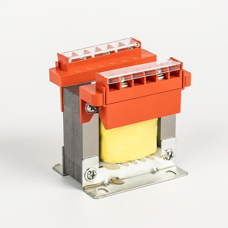
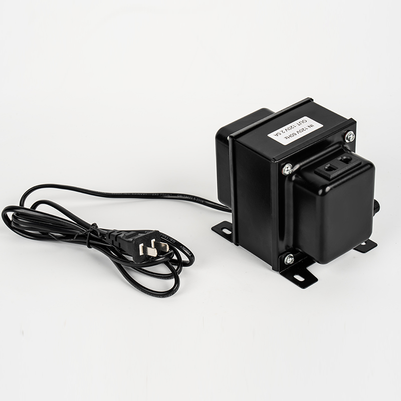
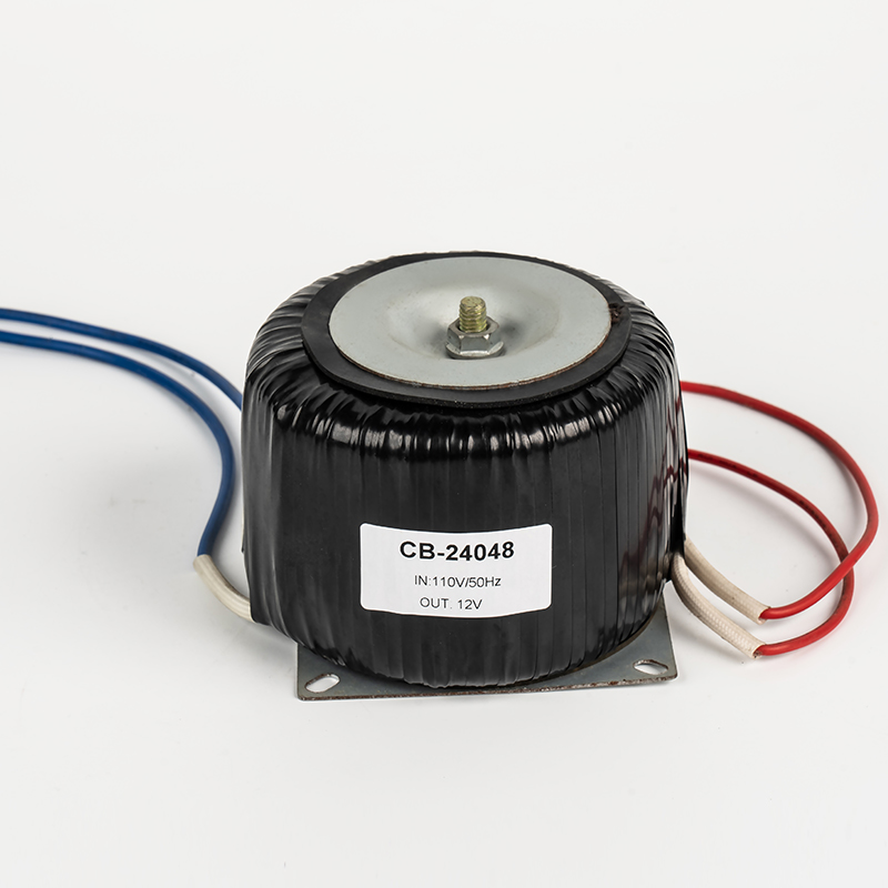
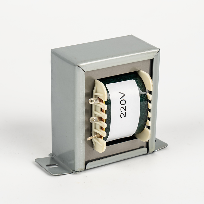
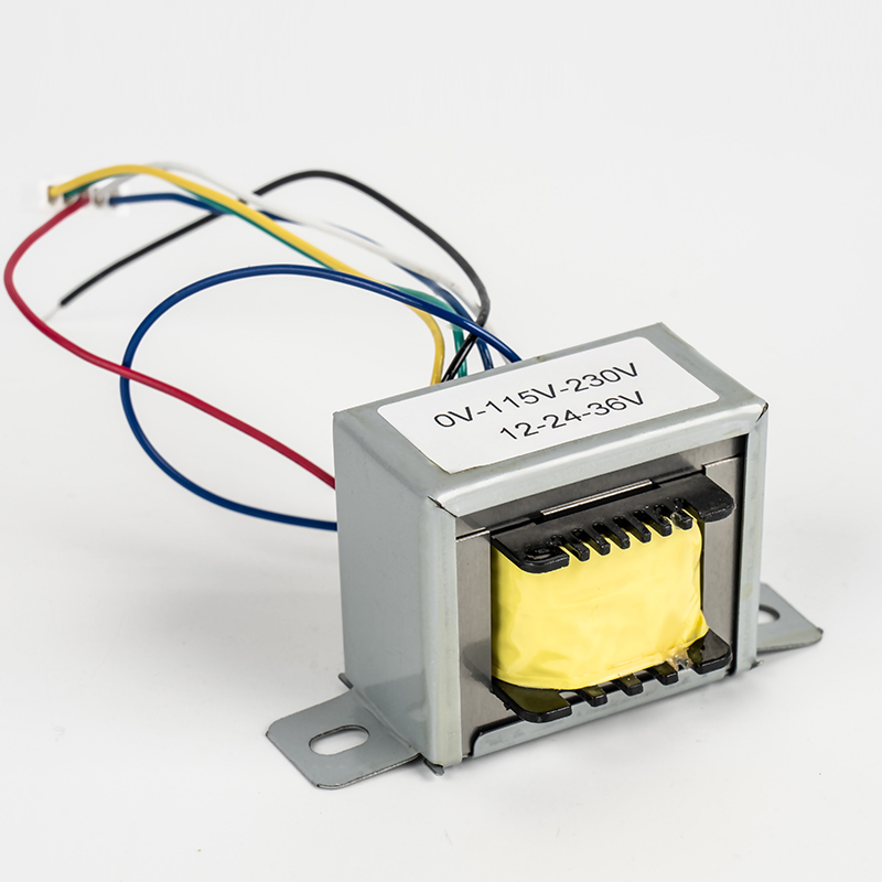
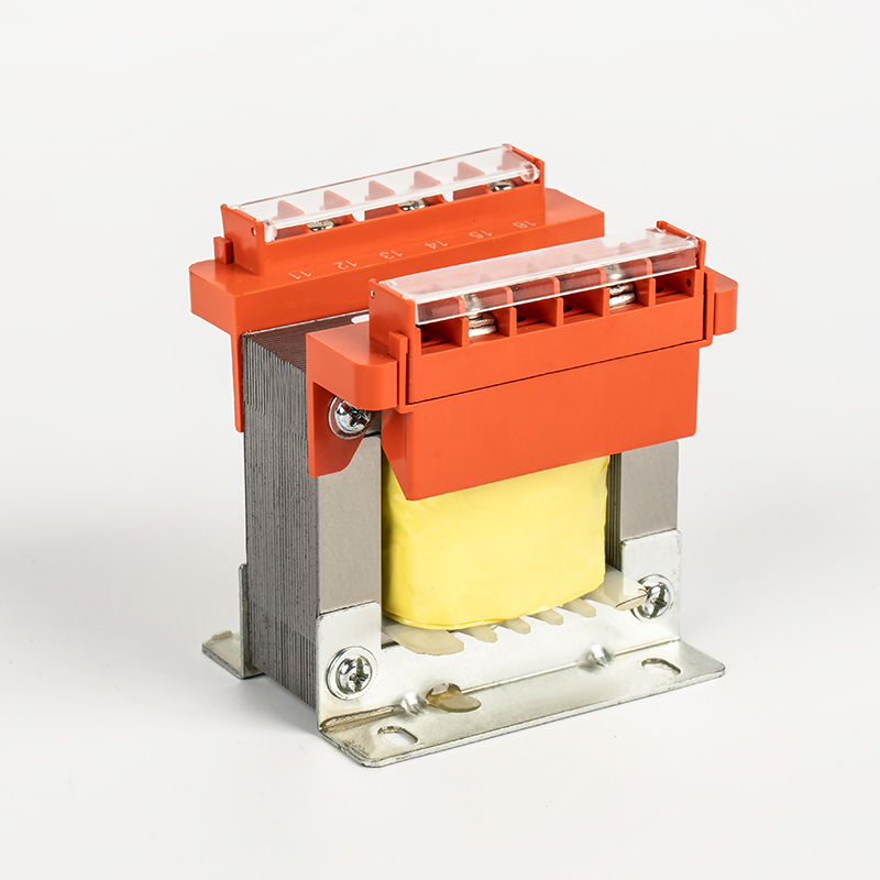
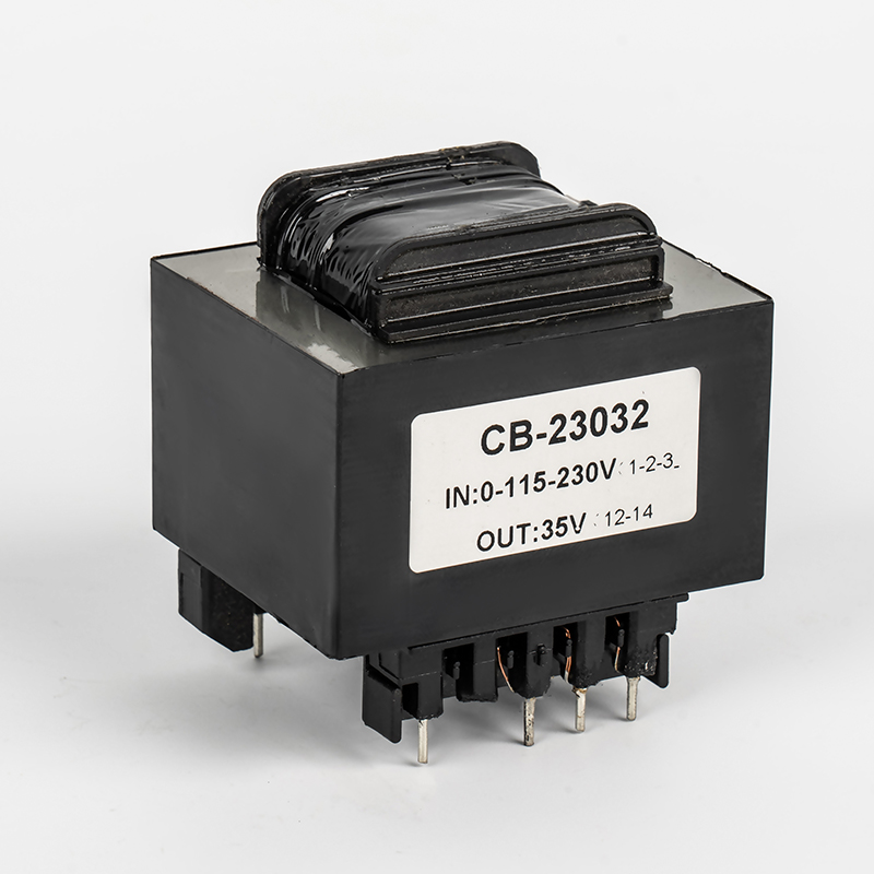
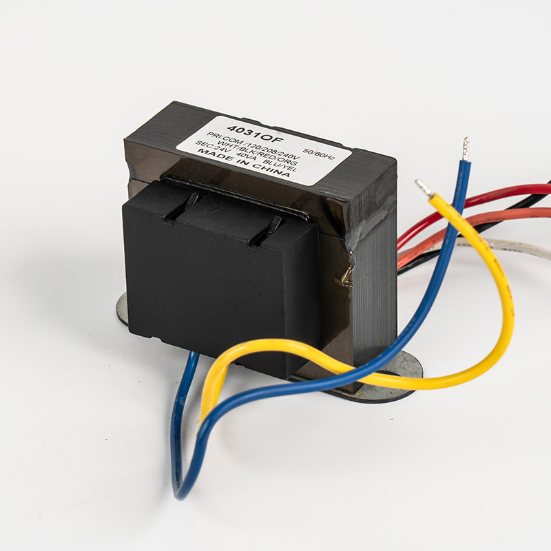
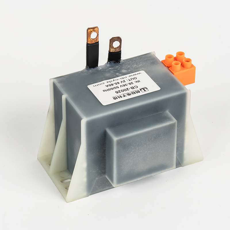
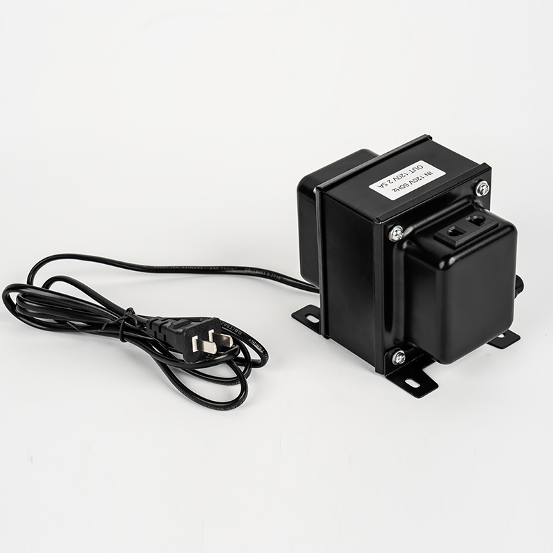
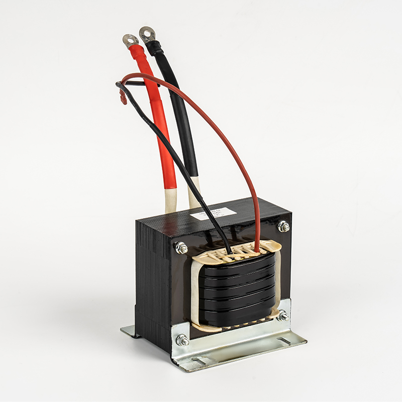
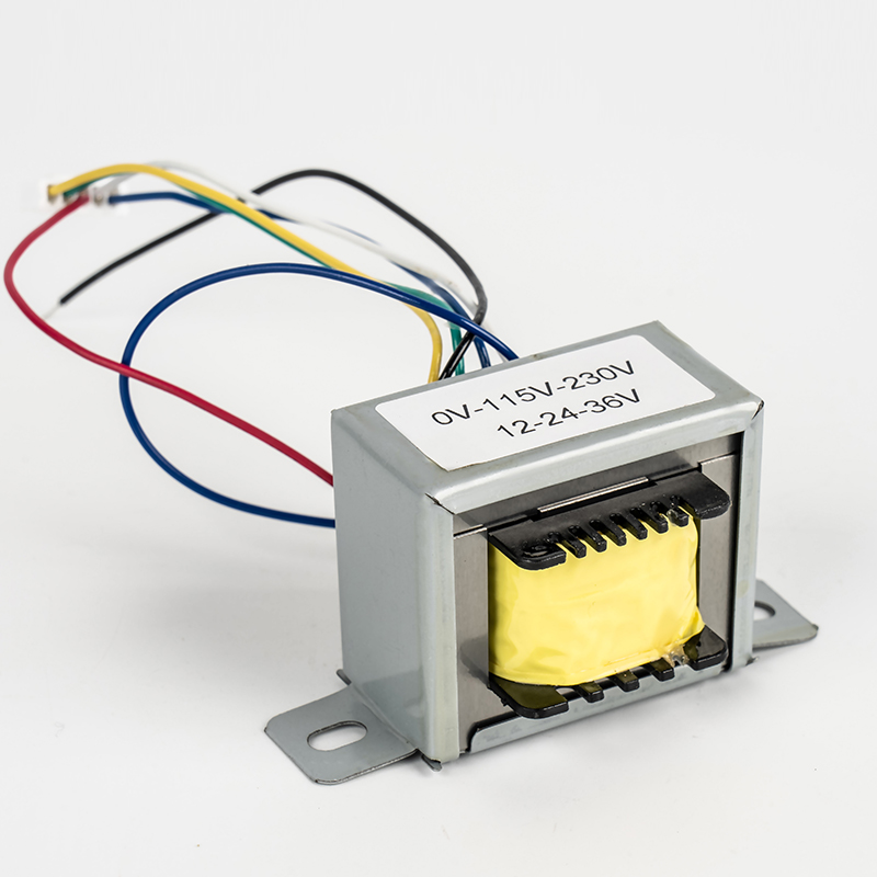
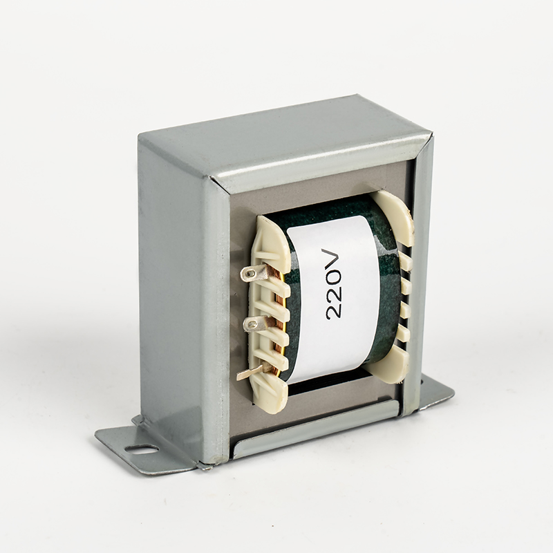
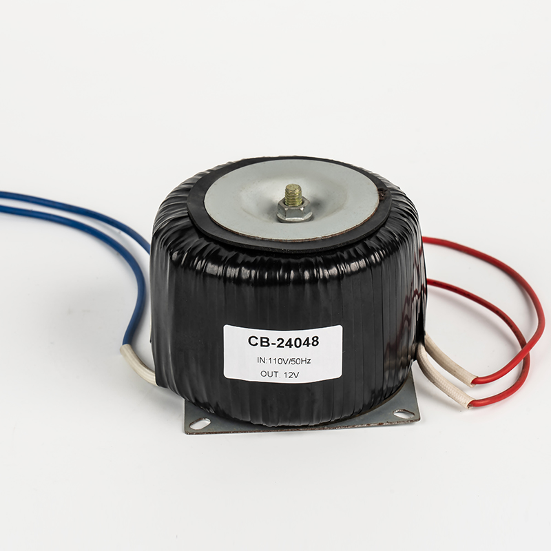
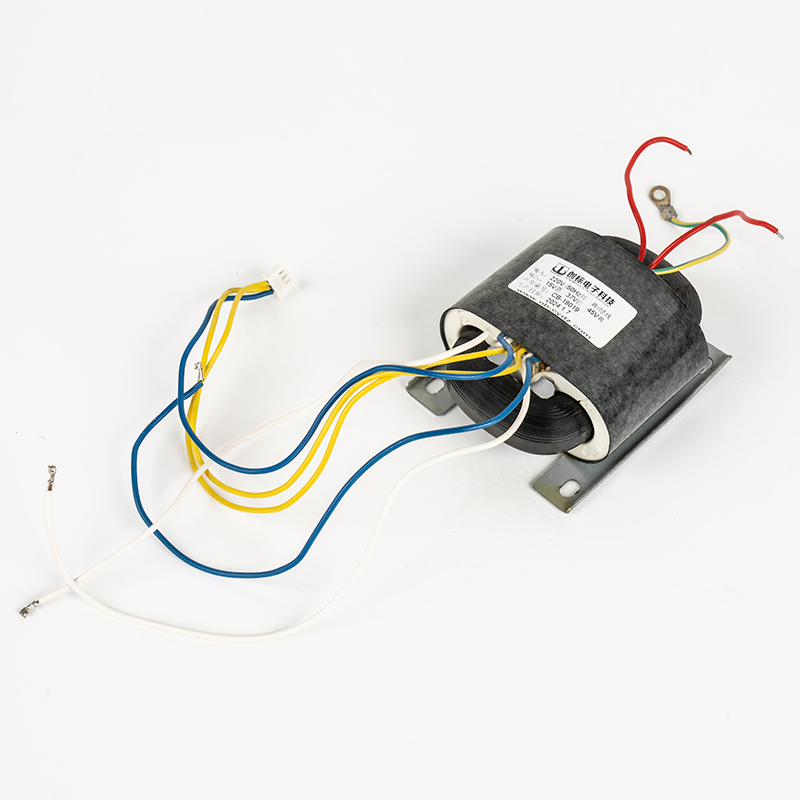
A stated kVA rating only performs as expected when the winding structure, core material and cooling method match the load profile. An EI transformer with a square transformer core is rugged and cost-effective for continuous industrial duty and welding equipment, while a toroidal transformer delivers a higher kVA-to-weight ratio, lower stray magnetic field and quieter operation, which suits audio, medical and instrumentation loads. A BK control transformer is purpose-built for control circuits and machine tool panels where multiple low-voltage secondary taps are needed at a modest kVA rating, and an isolation transformer prioritizes safety separation between primary and secondary windings rather than maximum power density. Matching the winding style to the duty cycle is as important as matching the number itself.
Transformer Product Range Browse core winding styles used to build the kVA rating your load profile calls for, from control circuits to isolated power stages.
Safety Margin and Derating Factors
Beyond the base load calculation, three variables commonly push the required kVA higher than the raw arithmetic suggests. Motor starting current can reach three to seven times the running current for a fraction of a second, and an undersized low-frequency transformer or ei inverter will sag voltage badly during that surge. Ambient temperature above 40 degrees Celsius reduces the safe continuous kVA a given transformer can deliver, so units installed in enclosed cabinets or hot climates should be derated by roughly 5 to 10 percent per 10 degrees above the rated ambient. Duty cycle also matters: a transformer feeding an intermittent welder can often run at a lower continuous kVA than one feeding a 24-hour production line at the same peak wattage.
Common Sizing Mistakes to Avoid
| Using watts instead of VA | Ignoring power factor understates the true load and leads to an undersized unit. |
| Ignoring inrush current | Motors and transformers themselves draw a brief surge at switch-on that a marginal rating cannot absorb. |
| Skipping future load | Adding one more machine later often exceeds a transformer sized with zero spare capacity. |
| Wrong winding style | Selecting a toroidal transformer for a rough industrial duty cycle, or an EI transformer where a toroid isolation transformer would run quieter and cooler. |
Working With a Transformer Factory
Once the target kVA and voltage ratios are set, a low-frequency transformer factory can confirm the design against your duty cycle, insulation class and mounting requirements rather than relying on a catalog figure alone. An experienced EI transformer factory or square transformer factory will typically ask for the primary and secondary voltages, frequency, ambient temperature, mounting orientation and whether the load is continuous or intermittent before confirming a final kVA and winding configuration. Sharing the equipment nameplate data or a simple load list, as outlined in the calculation steps above, is usually enough for an engineer to recommend the correct control transformer, isolation transformer or power transformer for the application.


Welcome To CHUANGBIAO
Address : No.420-3, Sanbei East Road, Guanhaiwei Industrial Zone, Cixi City, Ningbo, Zhejiang, China
Contact
- Tel: +86 186 6825 0703
- Email: linjian@nbcbdz.com
About us
Products
Copyright © Ningbo Chuangbiao Electronic Technology Co., Ltd.
All Rights Reserved. EI Transformer Manufacturer


