
 English
 中文简体
Transformer for Audio Amplifier Applications: A Practical Selection Guide
2026-10-30
Content
- 1 Two Transformer Roles That Are Frequently Confused
- 2 Specifying the Power Transformer
- 3 Impedance Matching in the Output Stage
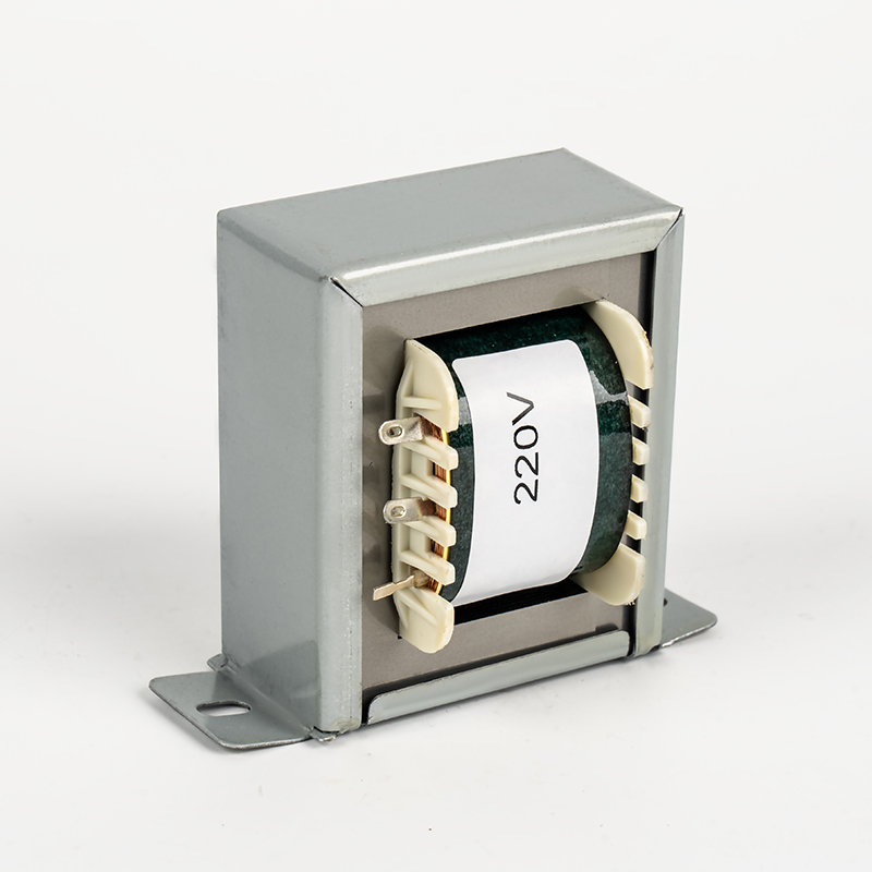
- 4 Core Format and Winding Style Compared
- 5 Hum, Noise and Bandwidth Limits
- 6 Build Quality and Test Points That Predict Field Failures
- 7 Buying: Custom Windings or Standard Stock
- 8 Frequently Asked Questions
A 25 W single-ended tube amplifier that hums at 100 Hz and rolls off below 70 Hz usually has a healthy circuit board. The problem normally sits in the magnetics: the power transformer radiates stray field into the input stage, and the output transformer runs out of primary inductance before the bass notes arrive. Both parts are ordered under the same line item, yet they are specified in completely different ways, and the cheaper part is often the one that forces a redesign.
Here is the short answer. For audio amplifier applications, specify the power transformer by VA rating, secondary voltage at full load, regulation, temperature rise and insulation class. Specify the output transformer by primary impedance, DC bias handling, core material and leakage inductance. Everything else, from lamination thickness to potting and shielding, is a refinement of those items.
Two Transformer Roles That Are Frequently Confused
An amplifier can contain both devices, and they are not interchangeable.
- The power transformer converts the mains supply into the high-voltage rail, typically 250 to 500 V DC after rectification, plus filament windings at 5 V or 6.3 V. It works at 50 or 60 Hz and is sized by volt-amperes, thermal rise and insulation class, and it also provides the galvanic isolation that keeps the chassis safe to touch.
- The output transformer couples the anode circuit of a tube output stage to a loudspeaker of 4, 8 or 16 ohm. It converts a high-voltage, low-current signal into a low-voltage, high-current one, and it blocks DC anode current from the voice coil.
Solid-state designs usually need only the first device, but transformers still appear in 70 V and 100 V distributed lines and in line isolation. In every case the specification logic is the same: match the electrical duty first, then control the thermal and magnetic behaviour.
Specifying the Power Transformer
Rating and Voltage
- Sum the high-voltage DC power and the filament AC power, then add 20 to 30 percent headroom. A transformer run continuously at its nameplate rating will sag and run hot.
- State secondary voltages at full load, not at no load. Small EI units commonly regulate at 10 to 15 percent, so a 300 V no-load winding may deliver 265 V once the amplifier draws current.
Thermal and Safety Limits
- Insulation class A (105 degrees C), B (130 degrees C) and F (155 degrees C) set the maximum hot-spot temperature. A class B unit with a 60 K rise behaves very differently in a sealed cabinet than in open air.
- Dielectric strength is verified with a hipot test, typically 1500 to 3750 V AC between primary and secondary, depending on the safety standard applied. For audio, radio and television type appliances, UL 1411 and IEC/EN 61558 are the usual references.
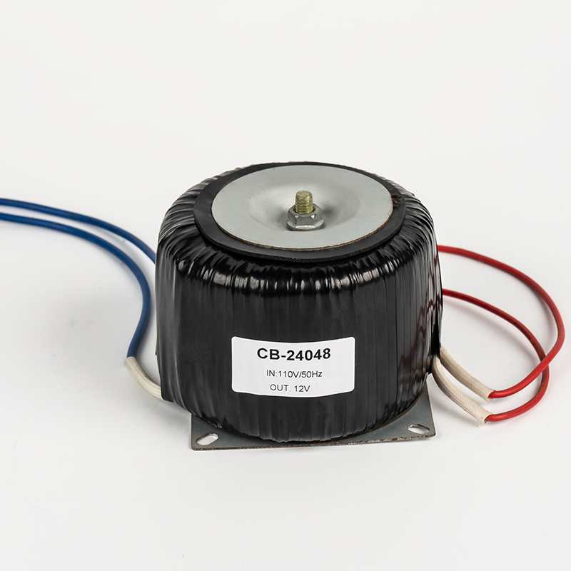
- Toroidal cores draw a high inrush current, so allow for a slow-blow fuse or an inrush limiting device in the design.
- A transformer designed for 60 Hz should not be used on 50 Hz at the same VA without risk of saturation, because core flux rises by roughly 20 percent. Either derate the load or specify the larger core from the start.
Impedance Matching in the Output Stage
The impedance ratio equals the square of the turns ratio. A 5 kohm to 8 ohm transformer therefore has a 625:1 impedance ratio and a 25:1 turns ratio. The primary impedance you choose changes both power output and distortion: 3.5 kohm usually delivers more watts with more second-harmonic distortion, while 8 kohm runs cleaner but lower. Check the value against the tube data sheet and the real speaker impedance curve, which dips and peaks well away from its nominal figure.
Single-Ended Versus Push-Pull
A single-ended stage carries DC anode current through the primary, which biases the core toward saturation. The core must be gapped, and the gap lowers effective permeability, so the stack has to be larger to reach the same primary inductance. Push-pull windings carry opposing DC currents; when the two halves are balanced the net flux is close to zero, so no gap is needed and interleaving can be used for wider bandwidth.
A practical target is 20 Hz to 20 kHz within 1 dB at moderate power, with low-frequency extension set by primary inductance and the source impedance of the output tube.
Core Format and Winding Style Compared
| Attribute | EI Laminated | Toroidal | C-Core |
|---|---|---|---|
| Typical use | Power and output duty, general purpose | Power transformers in compact chassis | High-grade output and power duty |
| Stray magnetic field | Higher, needs distance or shielding | Low, tight field containment | Moderate, lower than EI |
| Low-frequency extension | Good with a large enough stack | Good, but difficult to gap | Good, gap is practical |
| DC bias handling | Air gap cut in the stack, suits single-ended | Difficult, needs gapped or special core | Gap placed in the C joint |
| High-frequency behaviour | Interleaving cuts leakage inductance | Low leakage, higher capacitance | Low leakage with interleaving |
| Mechanical hum | Can buzz if laminations loosen | Quiet when potted, inrush noise on start | Moderate, improves when clamped |
Hum, Noise and Bandwidth Limits
- Mechanical hum comes from magnetostriction and loosening laminations. Vacuum varnish impregnation and potted toroids reduce it, and mounting the transformer at right angles to input wiring reduces inductive coupling into sensitive stages.
- An electrostatic shield, normally a single earthed copper foil turn between primary and secondary, reduces common-mode noise coupling.
- Low-frequency response is set by primary inductance and the driving impedance. High-frequency roll-off is set by leakage inductance and winding capacitance. Interleaving lowers leakage inductance, but more layers add capacitance, so this is a trade-off rather than a free improvement.
- A 1:1 or 600:600 ohm isolation transformer breaks a ground loop without cutting the signal path, and it converts an unbalanced line to a balanced one at the same time.
Build Quality and Test Points That Predict Field Failures
Most transformer failures that reach the customer are process failures rather than design failures, and they show up in a small number of places.
- Winding tension and layer insulation. CNC winding with consistent tension prevents layer slip and narrows the unit-to-unit variation in leakage inductance.
- Creepage and clearance. Margin tape and sleeving decide whether the part still passes a hipot test after months of thermal cycling, not only on the first sample.
- Vacuum varnish impregnation, which fixes the windings, blocks moisture ingress and reduces audible buzz.
- Routine testing on every unit: turns ratio, primary inductance, DC resistance balance, polarity, insulation resistance and dielectric strength, rather than sample-only checks.
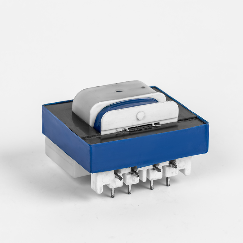
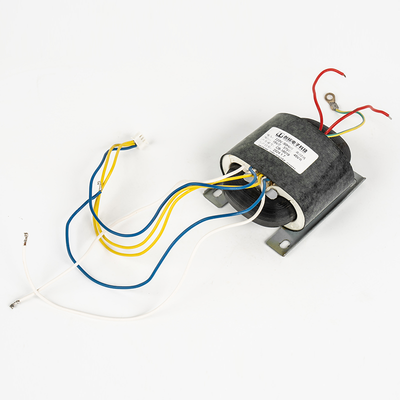
Our workshop has manufactured electronic transformers since 2010, with EI types as the main line alongside toroidal, C-type, medical, audio, high-voltage, industrial control and high-frequency designs. Material comes from approved suppliers under an ISO 9001 system, and each transformer is inspected and tested before dispatch. You can read more about the design-to-delivery process behind these transformers if you want to review the flow before placing an order.
Frequently Asked Questions
Is a toroidal transformer always better for audio?
No. Toroids have lower stray field and lower leakage inductance, which helps power supplies and hum performance. For output duty, EI and C-core formats remain easier to gap, run cooler in push-pull designs and are simpler to interleave for a specific bandwidth target.
Why does my output transformer saturate or buzz?
The usual causes are unbalanced push-pull windings, DC current in a core that was never gapped, or a lamination stack that lost compression. Check the DC resistance balance between halves and confirm that the core was designed for the standing current.
Can a 60 Hz transformer run on 50 Hz mains?
Only with derating. Flux rises by about 20 percent when frequency drops, so the core moves closer to saturation: expect more magnetizing current, more heat and possible audible buzz. Specify a 50 Hz design or reduce the load.
Do solid-state amplifiers need transformers?
Normally not at the output. They still need a mains power transformer, and transformer coupling is still used in 70 V and 100 V distributed lines and in line-level isolation and balancing.
Treat both devices as separate purchases with separate specification sheets. Fix the power transformer by VA, loaded secondary voltage, regulation and insulation class; fix the output transformer by primary impedance, DC bias handling and leakage inductance. Then confirm tolerances, hipot criteria and sample approval in writing. That sequence removes most of the hum, early saturation and short service life that appear later on the test bench, and it keeps a second design iteration out of the project budget.


Welcome To CHUANGBIAO
Address : No.420-3, Sanbei East Road, Guanhaiwei Industrial Zone, Cixi City, Ningbo, Zhejiang, China
Contact
- Tel: +86 186 6825 0703
- Email: linjian@nbcbdz.com
About us
Products
Copyright © Ningbo Chuangbiao Electronic Technology Co., Ltd.
All Rights Reserved. EI Transformer Manufacturer


