
 English
 中文简体
Medical Equipment Transformer Requirements: IEC 60601, Leakage Current, and Sourcing
2026-11-10
Content
- 1 The Short Answer: Medical Grade Means Evidence, Not a Label
- 2 Why Leakage Current Drives the Whole Design
- 3 Insulation, Creepage, and the Details That Fail Late
- 4 Testing and Documentation: What to Ask Before You Approve a Sample
- 5 A Practical Selection Checklist
- 6 Common Mistakes That Show Up Late
- 7 FAQ
A 60 W diagnostic monitor is almost ready for IEC 60601-1 testing when the lab asks for the transformer's leakage-current data. The part on the bench is a general-purpose 100 VA transformer with a 1.5 kV hipot label. It may power the board, but it was never designed to be evaluated as part of a medical device. That is where schedules slip.
The short answer: a transformer used in medical equipment has to be selected and documented against the device standard, usually IEC 60601-1, with UL 60601-1 or ANSI/AAMI ES60601-1 used in the US. The transformer itself is not approved just because it has a medical label. The final device has to show acceptable leakage current, dielectric strength, insulation, creepage and clearance, temperature rise, and construction. For medical isolation transformers used in medical locations, IEC 61558-2-15 is also commonly referenced.
The Short Answer: Medical Grade Means Evidence, Not a Label
A medical-grade transformer is built around four requirements: low leakage current, a robust insulation system, controlled construction, and traceable test data. A catalog medical sticker is not enough; the part has to fit the final device's working voltage, pollution degree, overvoltage category, and patient-connection type.
| Requirement | What it means in practice | What to verify |
|---|---|---|
| Leakage current | Current flowing through insulation, capacitance, and stray paths to earth or the patient. | Device-level test data for normal and single-fault conditions; target depends on Type B, BF, or CF. |
| Dielectric strength | The insulation must withstand a high-voltage stress without breakdown. | Type-test report and routine hipot records; test voltage and duration must match the insulation class. |
| Insulation system | Basic, supplementary, double, or reinforced insulation between live parts and accessible parts. | Insulation diagram, material data, and evidence that the transformer construction matches the diagram. |
| Creepage and clearance | Physical distance across surfaces and through air between conductive parts. | Drawings and sample inspection against working voltage, pollution degree, and material group. |
| Temperature rise | The transformer must stay within its insulation class and the device's thermal limits. | Temperature-rise test at rated load and worst-case ambient; check mounting and enclosure conditions. |
| Documentation | The supplier must provide consistent evidence, not a one-page certificate. | Controlled drawings, test reports, component certificates, and change notification. |
The practical takeaway is simple: decide the leakage-current target and insulation class before you lock the mechanical design. If the transformer is 2 mm too tall and the creepage path is 1 mm short, the enclosure change comes later and costs more.
Why Leakage Current Drives the Whole Design
Leakage current is the first requirement that changes the transformer's physical shape. In a medical device, current can flow from the mains through the transformer's interwinding capacitance, through Y-capacitors, and through stray capacitance to earth or to the patient. The transformer is only one path, but it is often the path that limits the rest of the design.
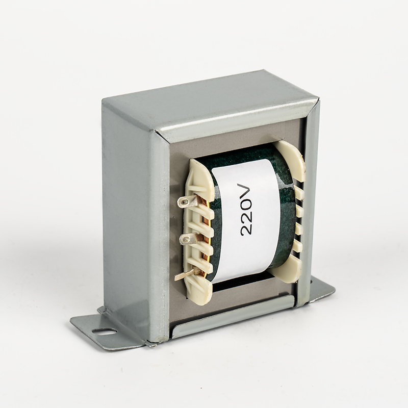
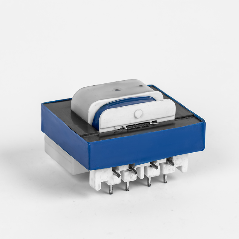
Two design choices matter. First, a split-bobbin or chambered construction increases the distance between primary and secondary and lowers capacitance. Second, an electrostatic shield, tied to a defined potential, can divert high-frequency noise. Neither choice is free: shielding adds a lead and a test step, and a larger bobbin can push the transformer out of a tight enclosure.
For patient-connected parts, the Type B, BF, or CF classification changes the allowable patient leakage current and the isolation level. A CF application is not the place to discover that the transformer's secondary is referenced to earth through a mounting screw. Ask for the leakage-current test method, not just a low-leakage claim.
Insulation, Creepage, and the Details That Fail Late
Medical equipment requirements usually push designers toward reinforced insulation between primary and secondary. That means two layers of insulation, or one layer plus a reliable barrier, with the creepage and clearance dimensions supported by the bobbin, margin tape, and potting. The exact numbers come from the working voltage, pollution degree, material group, and the standard's tables; they are not a single number that fits every 230 V device.
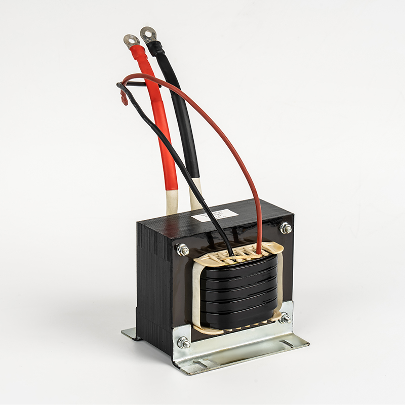
Three construction details deserve a place on the drawing: margin tape width at the bobbin ends, the distance from the core to the winding, and the routing of the shield lead. A sample can pass a hipot test and still fail a construction review because the creepage path is pinched by a cable tie or because the varnish bridge is too narrow. For a device that will be audited, the drawing and the physical part need to match.
Temperature rise is part of the same conversation. A transformer that runs hot in a sealed enclosure can change the insulation's life and trigger a redesign of the enclosure vents. Specify the ambient temperature, duty cycle, and mounting orientation. If the transformer is potted, confirm that the potting is qualified for the insulation class and does not hide a thermal problem.
Testing and Documentation: What to Ask Before You Approve a Sample
Ask for three sets of evidence: design evidence, routine test data, and component approvals. Design evidence includes the insulation diagram, creepage and clearance calculations, and type-test reports for dielectric strength, leakage current, and temperature rise. Routine test data should show that every unit was hipot tested and checked for no-load and full-load performance. Component approvals include the transformer's recognized or certified status, plus any CQC, RoHS, or REACH declarations that apply.
Manufacturers such as Ningbo Chuangbiao Electronic Technology build medical transformers around a process that covers design, incoming material control, manufacturing, quality assurance, and delivery, with ISO 9001 as the working quality system. That is useful context, but it does not replace the device-level test. A supplier's ISO certificate tells you the factory has a process; it does not tell you that the transformer meets the leakage-current limit in your specific application.
When you request a custom transformer, send the working voltage, isolation type, leakage-current target, ambient temperature, duty cycle, mounting constraints, and the standard the final device will be tested to. A drawing with only VA and turns ratio leaves the most expensive requirements unresolved.
A Practical Selection Checklist
Use this list before you ask for a quote. It separates a transformer that will pass a desktop test from one that will survive a device submission.
- Input voltage and tolerance: 100-240 V, 50/60 Hz, brownout, and overvoltage conditions.
- Output: VA rating, voltage, current, regulation, duty cycle, and start-up load.
- Isolation: 1:1 isolation or step-down, working voltage, and reinforced or double insulation.
- Leakage current: target in microamps, Type B, BF, or CF, and normal versus single-fault condition.
- Construction: split bobbin, electrostatic shield, margin tape, potting, mounting, and lead routing.
- Thermal: ambient temperature, allowable rise, insulation class, and enclosure airflow.
- Agency: IEC 60601-1, UL 60601-1, IEC 61558-2-15 where applicable, CQC, RoHS, and REACH.
- Documentation: controlled drawing, test reports, certificate scope, and change notification.
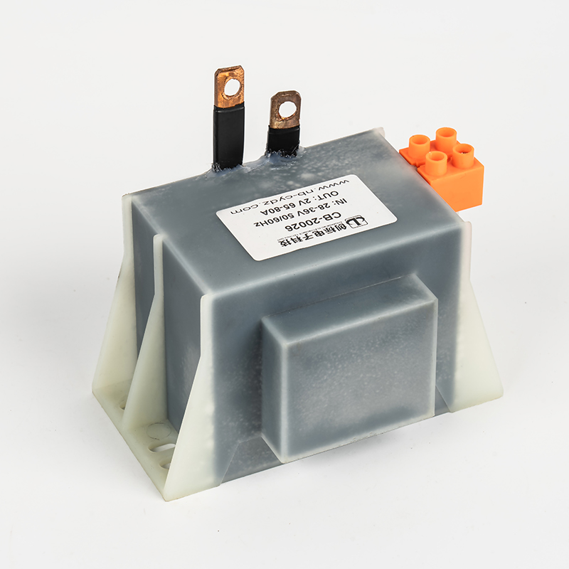
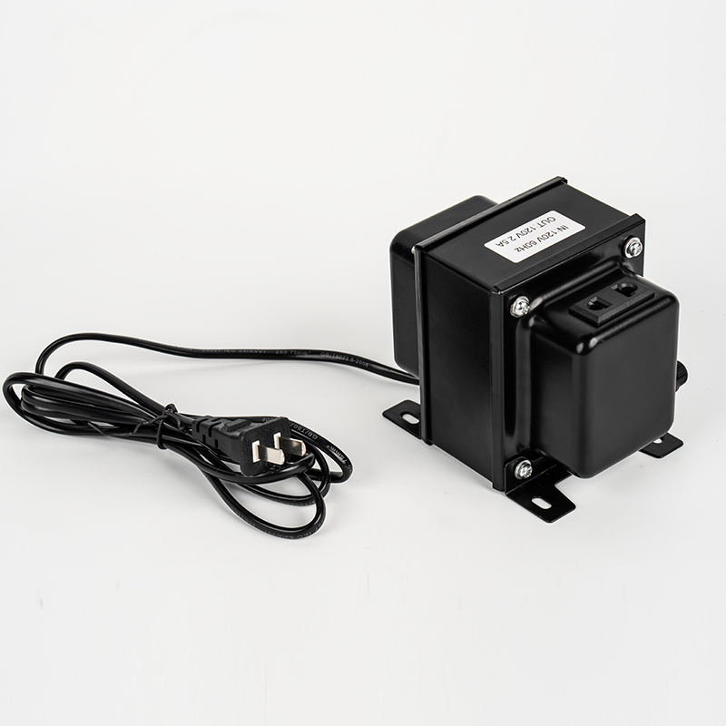
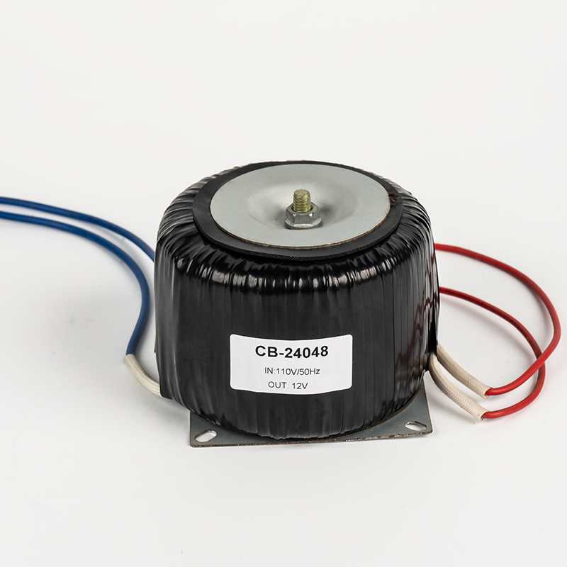
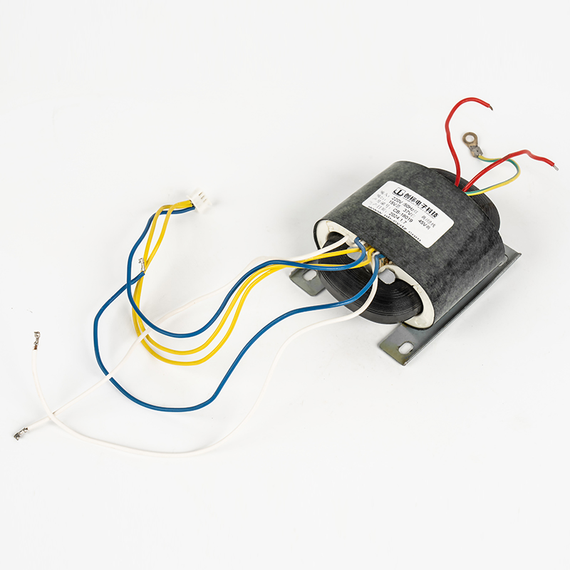
The 1:1 isolation transformer is a useful example. It can isolate the neutral from earth and simplify a design that uses a standard PC or monitor inside a medical system. The trade-off is size and weight. A 1:1 transformer that handles 250 VA to 2,400 VA can be much larger than the switching supply it supports. Plan the mounting and thermal path early.
Common Mistakes That Show Up Late
- Buying a general-purpose transformer and assuming a hipot sticker equals medical approval.
- Treating the transformer's leakage current as the whole system's leakage current.
- Waiting until the enclosure is frozen to check creepage and clearance.
- Forgetting the single-fault condition and the patient-connected circuit.
- Accepting a certificate without the test report or the matching drawing revision.
- Ignoring the difference between prototype and production; every unit needs routine testing.
The last mistake is the most expensive. A prototype can be hand-built with extra tape and a longer lead. Production will not be hand-built unless the drawing and the work instruction force it.
FAQ
Does every transformer inside a medical device have to be labeled medical grade?
No. The device standard sets the requirements. A general-purpose transformer can be acceptable if it is evaluated in the final application and meets leakage current, insulation, and construction requirements. In practice, a transformer designed for medical use makes the evaluation easier and gives you better documentation.
What leakage current should I specify?
Specify the limit from the applicable clause and the patient-connection type, then add a design margin. Do not specify only low leakage. State the test method, the condition, and the maximum current at the device level.
Is a 1:1 isolation transformer enough for patient safety?
No. A 1:1 transformer isolates the supply, but patient safety also depends on insulation, creepage, grounding, and the patient-connected circuit. The transformer is one part of the isolation strategy, not the whole strategy.
What documents should come with the transformer?
Request the insulation diagram, dielectric test report, leakage-current data, temperature-rise report, applicable certificates, and the controlled drawing. For production, request routine test records and a change-notification process.
Medical transformer requirements are not a single number. They are a chain: the device standard defines the leakage current and insulation limits, the transformer design gives you the physical margin, and the test records prove that the chain holds. Start with the standard and the patient-connection type, then choose the transformer. That order saves more time than a last-minute sample swap.


Welcome To CHUANGBIAO
Address : No.420-3, Sanbei East Road, Guanhaiwei Industrial Zone, Cixi City, Ningbo, Zhejiang, China
Contact
- Tel: +86 186 6825 0703
- Email: linjian@nbcbdz.com
About us
Products
Copyright © Ningbo Chuangbiao Electronic Technology Co., Ltd.
All Rights Reserved. EI Transformer Manufacturer


